
Dissolved air flotation units.
Micro-bubble flotation for suspended solids, oil and grease — supplied as full-tank nano, shallow-tank and horizontal-flow units and sized to your flow and discharge standard.
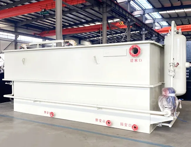
What a dissolved air flotation unit is, and what the site still does
A dissolved air flotation unit takes suspended solids, oil, grease and gelatinous matter out of water by attaching them to bubbles. A recycle stream of water is saturated with air at about 0.5 MPa and released into the tank, where the pressure drops and the air comes out as a dense cloud of fine bubbles; the bubbles attach to the solids and the oil and lift them to the surface, where a skimming device removes them as float, and matter denser than water settles to the bottom and is drawn off to the sludge side of the unit. The unit is assembled and tested at our factory, so on site only the foundation, the placement, the inlet and outlet connections, the power feed to the control panel and the commissioning support remain.
The process removes what floats or can be made to float. It does not remove dissolved salts, ammonia or soluble organic matter that is not attached to a particle or an oil droplet, and it is not a replacement for a biological stage where those loads are the problem. It also does not turn the float into a disposable cake by itself: the float is a sludge with its own handling route.
Full-tank, shallow or horizontal-flow: how the three configurations differ
The three ranges differ mainly in tank geometry. The full-tank nano design spreads the released air across the whole tank instead of a single contact zone, so the solids and oil meet a large bubble surface before the flow leaves the separation zone; flotation, sedimentation and thickening happen in one tank. The shallow high-rate design keeps the effective water depth between 600 and 750 mm, which shortens the retention time and raises the surface loading the tank can carry. The horizontal-flow design passes the flow from one end of the separation zone to the other, which suits high suspended-solids loads and steady sludge scraping.
- Full-tank nano — industrial and domestic sewage where flotation, settling and thickening are wanted in one tank, and where the float and the settled sludge both have to be collected.
- Shallow high-rate — high-density sewage and municipal pretreatment ahead of a biological stage, where a short retention time and a small footprint matter. The shallow air flotation detail page covers that configuration on its own.
- Horizontal-flow — high suspended-solids loads and duties where a long separation path and steady scraping suit the sludge.
Dissolved air flotation is not always the right stage. If the problem is dissolved organic matter, nitrogen or phosphorus, the answer is a biological process, not a bigger flotation tank. If the stream carries heavy grit, rags or debris, that material has to be screened or settled out first. Where land is available and the discharge standard is loose, sedimentation and clarification can be the better value. The selection and sizing guide takes the choice from the duty rather than from the product name.
Start with the flow, then check the solids and oil load
Design flow alone does not size a dissolved air flotation unit. Two streams with the same cubic metres per hour can need different tank areas, different recycle rates and different chemical doses, because the solids load, the oil load and the wastewater temperature move the duty.
- Flow — average design flow and peak flow, with the peak factor stated rather than assumed.
- Solids — suspended solids as a concentration and as a daily load, plus the target suspended-solids figure at the outlet.
- Oil and grease — free oil, emulsified oil and the expected maximum, since the emulsified fraction is what chemical assistance is for.
- Wastewater — temperature range, density, salinity and any stream that could inhibit the chemistry.
- Chemistry and target — coagulant and polymer where they are used, and the discharge or reuse standard the unit has to meet.
What does not suit a flotation unit
Dissolved salts, ammonia and soluble organic matter pass a flotation unit. Heavy grit and debris damage the recycle pump and blind the release system, so they are removed upstream. Free product that has value as a product is recovered, not treated. The influent quality chart gives the input side of the design.
The surface loading figure, recomputed from the published table
For the shallow CXQF range the catalogue publishes the maximum capacity in cubic metres per day and the disc diameter in millimetres. The surface loading is the flow divided by the plan area: capacity in m³/d divided by 24 gives m³/h, the disc area is π/4 × diameter², and the surface loading is the flow over that area in m³/m²·h. Across the six published models the result is about 4.4–5 m³/m²·h.
One model worked through: CXQF-100 is published at 2200 m³/d, which is 2200 ÷ 24 = 91.7 m³/h. Its disc diameter is 5000 mm, so the area is π/4 × 5.0² = 19.63 m². The surface loading is 91.7 ÷ 19.63 = 4.67 m³/m²·h. The same capacity and diameter values, and the same formula, are the ones the DAF sizing calculator uses, so the figure on this page and the figure the calculator works from cannot drift apart.
The published removal references for the shallow range are suspended-solids removal above 90 percent and a floated sludge concentrated to about 35 percent. Those are catalogue reference values under the stated duty, not a project guarantee; the removal on your stream is confirmed by test or by a documented reference case before it is written into a contract. The capacity, the chemical dose and the float concentration are likewise confirmed for the project from the influent, the target standard and the site conditions.
Where our supply ends and your site work begins
The unit is assembled and tested at our factory before shipment, and the commercial offer fixes the exact scope line. What is in our supply and what stays on site is what the project plan has to carry.
- In our supply — the flotation tank with its contact and separation zones, the saturator vessel, the recycle pump, the air compressor, the skimming or scraper drive and the control panel.
- Your site work — the foundation and drainage, the inlet and outlet pipework to the unit flanges, the power cable to the control panel, the lifting and placement of the unit, and any chemical dosing station supplied separately.
- Fixed in the offer — the interface list, the exact scope line and any item supplied by a nominated vendor are stated in the offer, not left to the site to discover.
It is a factory-tested package, not a turnkey building. Installation is confirmed from the site layout and the foundation drawing, and the transport envelope is confirmed with each order against the packed dimensions and the port of discharge.
Acceptance is written into the contract: factory acceptance tests before shipment, site acceptance tests after installation, and a performance test at design load, with the removal guarantee, the sampling point and the test method fixed for the project against the receiving works' standard. A failed result is rectified and retested as agreed. Acceptance records are project documents, not published specifications; when you compare quotations, ask for the acceptance section of the contract.
What leaves the unit besides treated water
Two streams leave the unit as sludge. The float skimmed from the surface carries the solids and oil that were lifted, and the settled sludge drawn from the bottom carries the denser matter. The float is a sludge in its own right, with a volume and a handling route to design, and the settled sludge is a second one.
- Float — thickened or dewatered before disposal; its concentration depends on the feed solids, the chemical dose and the skimming depth, and the catalogue reference of about 35 percent is a stated-duty figure rather than a project result.
- Settled sludge — drawn from the hopper and handled with the plant sludge.
- Disposal route — set by the local rule and the waste classification, and carried out by a licensed contractor; the equipment collects and contains the streams, it does not decide their legal outlet.
The sludge dewatering range takes the float and the settled sludge on to a handleable cake, and the route from the cake to its final destination is confirmed for the site.
Running the unit: chemicals, power and maintenance
Where the oil is emulsified, the unit runs with chemical assistance: a coagulant to destabilise the emulsion and a polymer to build a float that can be skimmed. The dose is set on the actual water by a bench test, not copied from a table, and the coagulation and flocculation jar test is how that dose is established.
The continuous power demand is dominated by the recycle pump and the air compressor, with the scraper drive a smaller and intermittent load. Installed power is fixed per project from the model and the duty; the page does not publish a single connected load for the range. Maintenance centres on the saturator, the release device and the skimming assembly, and the routine for a packaged plant is set out in commissioning and operating a packaged plant.
The documents that answer the performance question
The model table is a catalogue document, and on its own it answers the capacity question but not the performance question. What supports a performance claim is a test report on a comparable stream, the factory test record for the unit, the outline and foundation drawings, the O&M manual and the spare-parts list.
- Catalogue table — model, capacity, dissolved-air water and dimensions, as published.
- Factory test record — the assembly and test carried out before shipment, for the unit actually built.
- Drawings — outline, foundation and interface drawings issued for the project.
- Manual and spares — operating manual, control and alarm list, and the spare-parts list.
- References — project cases only where the customer has agreed to be named; otherwise the evidence is the test record rather than a logo wall.
For any quoted removal figure, ask which stream it was measured on and under which conditions. The working-principle article explains what the mechanism can and cannot deliver, and the surface loading and hydraulic loading article sets out how the loading figure is derived.
Full-tank nano dissolved air flotation (CXCF series)
In the full-tank design the released air is spread across the whole tank rather than a single contact zone, so suspended solids, oil and grease meet a large bubble surface area before the flow leaves the separation zone. The unit combines flotation, sedimentation and thickening in one tank, and the air it releases is roughly 20 to 40 times the volume of the recycled dissolved-air water. It is intended for removing suspended solids from industrial and domestic sewage and is used in chemical plants, textile printing and dyeing, electroplating, paper making, oil refining, food processing and leather manufacture. A pump charges air into the saturator at about 0.5 MPa; on release, the dissolved air forms a dense cloud of bubbles that absorb suspended matter as it rises, so suspended solids and COD are removed.
| Model | Capacity (m³/h) | Dissolved-air water (m³/h) | Return pump (kW) | Scraper (kW) | Air compressor (kW) | Saturator vessel (mm) | Dimensions L × W × H (m) |
|---|---|---|---|---|---|---|---|
| CXCF-5 | 5 | 4.5 | 3 | 0.12 | 1.5 | Φ400 | 3.8 × 2.5 × 2.3 |
| CXCF-10 | 10 | 4.5 | 3 | 0.12 | 1.5 | Φ400 | 4.6 × 2.5 × 2.3 |
| CXCF-20 | 20 | 8 | 5.5 | 0.12 | 1.5 | Φ500 | 5.2 × 2.9 × 2.3 |
| CXCF-25 | 25 | 8 | 5.5 | 0.12 | 1.5 | Φ500 | 5.5 × 2.9 × 2.3 |
| CXCF-30 | 30 | 12.5 | 5.5 | 0.12 | 1.5 | Φ500 | 6 × 2.9 × 2.3 |
| CXCF-50 | 50 | 25 | 7.5 | 0.37 | 2.2 | Φ600 | 7 × 3.3 × 2.5 |
| CXCF-80 | 80 | 25 | 7.5 | 0.55 | 3 | Φ600 | 8 × 3.8 × 2.5 |
Dimensions are reference values reproduced from our catalogue and are approximate. Final dimensions and weights are confirmed against the site conditions and the actual build.
Super-efficiency shallow dissolved air flotation (CXQF series)
The shallow-tank design keeps the effective water depth between 600 and 750 mm, and at the published capacities below the disc area corresponds to a surface loading of about 4.4–5 m³/m²·h. The shallow tank makes floating impurities easy to collect, which suits high-density sewage, and both the water level and the skimming depth are adjustable. Suspended-solids removal is above 90 percent and the floated sludge can be concentrated to about 35 percent. The range is widely used in municipal sewage, paper making, wastepaper recovery, painting, dyeing, chemical engineering, food processing, brewing, tanning, oil refining and pharmaceuticals; in many cases it can take the place of biochemical treatment equipment, since one round of physical and chemical treatment brings the water to standard, and it is also applied as pre-treatment in water works.
| Model | Max capacity (m³/d) | Diameter (mm) | Total disc height (mm) |
|---|---|---|---|
| CXQF-65 | 1500 | 4000 | 1100 |
| CXQF-100 | 2200 | 5000 | 1100 |
| CXQF-200 | 4500 | 7000 | 1125 |
| CXQF-250 | 6000 | 8000 | 1150 |
| CXQF-320 | 7500 | 9000 | 1150 |
| CXQF-420 | 10000 | 11000 | 1200 |
Dimensions are reference values reproduced from our catalogue and are approximate. Final dimensions and weights are confirmed against the site conditions and the actual build.
Horizontal-flow dissolved air flotation (CXPF series)
In the horizontal-flow design the flow crosses the separation zone from one end of the tank to the other, a configuration that suits high suspended-solids loads and steady sludge scraping. It is intended for removing suspended solids, oil and gelatinous substances and is applied in slaughterhouses, electroplating plants, chemical engineering, paper making, oil refining, and textile, printing and dyeing wastewater treatment. The system dissolves air in the water under pressure; as the pressure is released, the bubbles adhere to suspended matter and lift it to the surface, where a skimming device removes it, while denser matter descends and is released to the sludge tank. At the 0.5 MPa saturating pressure, suspended-solids removal is above 90 percent and COD removal above 70 percent.
| Model | Capacity (m³/h) | Dissolved-air water (m³/h) | Main motor (kW) | Scraper (kW) | Air compressor (kW) | Saturator pump model | Air compressor model | Saturator vessel (mm) | Dimensions L × W × H (mm) |
|---|---|---|---|---|---|---|---|---|---|
| CXPF-5 | 4–5 | 1.5–2 | 3 | 0.55 | 1.5 | V-0.1/8 | 11/2GC5-1 | Φ400 × 1000 | 3000 × 2200 × 1900 |
| CXPF-10 | 8–10 | 2–3 | 3 | 0.55 | 1.5 | V-0.14/7 | 11/2GC-5 × 2 | Φ500 × 1500 | 4000 × 2200 × 2400 |
| CXPF-15 | 10–16 | 3.5–5 | 3 | 0.55 | 2.2 | V-0.14/7 | 11/2GC-5 × 2 | Φ500 × 1500 | 4500 × 2200 × 2400 |
| CXPF-20 | 15–21 | 5–7 | 7.5 | 0.55 | 2.2 | V-0.14/7 | 2GC-5 × 2 | Φ500 × 1500 | 5000 × 2700 × 2400 |
| CXPF-30 | 20–30 | 6–10 | 7.5 | 0.55 | 2.2 | V-0.14/7 | 21/2GC-5 × 2 | Φ500 × 1500 | 6000 × 2700 × 2400 |
| CXPF-40 | 30–40 | 8–13 | 7.5 | 0.75 | 2.2 | V-0.14/7 | 21/2GC-6 × 2 | Φ600 × 1800 | 6000 × 3100 × 2400 |
| CXPF-50 | 40–50 | 15–20 | 7.5 | 0.75 | 2.2 | V-0.14/7 | 1S65-40-200 | Φ600 × 1800 | 6500 × 3100 × 2400 |
| CXPF-60 | 50–60 | 18–27 | 7.5 | 0.75 | 2.2 | V-0.14/7 | 1S65-40-200 | Φ600 × 1800 | 7000 × 3100 × 2600 |
| CXPF-80 | 70–80 | 24–32 | 10 | 0.75 | 2.2 | V-0.14/7 | 1S80-65-160 | Φ600 × 1900 | 9000 × 3100 × 2600 |
| CXPF-100 | 90–105 | 30–35 | 10 | 1.1 | 3 | V-0.36/7 | 1S80-50-200 | Φ700 × 2000 | 11000 × 3100 × 2600 |
| CXPF-150 | 125–150 | 60–80 | 15 | 1.1 | 3 | V-0.36/7 | 1S150-80-400 | Φ700 × 2000 | 13000 × 3700 × 2600 |
| CXPF-200 | 175–200 | 80–100 | 15 | 1.1 | 3 | V-0.36/7 | 1S150-80-400 | Φ800 × 2100 | 14000 × 3700 × 2600 |
| CXPF-250 | 225–250 | 100–120 | 15 | 1.1 | 3 | V-0.36/7 | 1S150-80-400 | Φ800 × 2400 | 15000 × 3700 × 2600 |
| CXPF-300 | 280–300 | 120–180 | 22 | 1.1 | 3 | V-0.67/7 | 1S150-125-400 | Φ1000 × 2900 | 16000 × 3700 × 2600 |
Dimensions are reference values reproduced from our catalogue and are approximate. Final dimensions and weights are confirmed against the site conditions and the actual build.