
CXMWI-20 to CXMWI-500 · Medical series
Medical Waste Incinerators
Destroy infectious waste at the point of generation. Our dual-chamber incinerators offer dry flue-gas treatment without process water or wet treatment combinations; we select the configuration against your applicable emission limits.
- Incineration temperature
- ≥850 °C
- Flue-gas residence time
- ≥2.0 s
- Flue-gas treatment
- Dry / wet, selected by emission limits
Send waste type, daily volume and emission requirements. Reply within 1 business day.
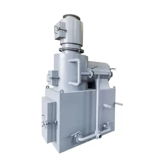
Choose by daily volume: CXMWI-20 to CXMWI-500
The medical waste range is sized from small clinics to large hospitals.
10–50 kg/h
CXMWI-20, CXMWI-30, CXMWI-50
Clinics, health centres, small hospitals
80–200 kg/h
CXMWI-100, CXMWI-150, CXMWI-200
Hospitals and pharmaceutical factories
200–500 kg/h
CXMWI-300-750, CXMWI-500
Large hospitals and pharmaceutical factories
CXMWI series — medical waste incinerators
Wide table: scroll sideways to see every column.
| Model | Incineration capacity | Size (L × W × H) | Combustion chambers | Typical use |
|---|---|---|---|---|
| CXMWI-20 | 10–20 kg/h | 1600 × 1200 × 1700 mm | Grate design, dual combustion chamber | Township health hospitals and small hospitals |
| CXMWI-30 | 20–30 kg/h | 1700 × 1250 × 2500 mm | Gasification pyrolysis with secondary high-temperature combustion | Township health hospitals and small hospitals |
| CXMWI-50 | 30–50 kg/h | 1800 × 1300 × 3000 mm | Gasification pyrolysis with secondary high-temperature combustion | Health clinics, sanitary waste and small to medium-size hospitals |
| CXMWI-100 | 80–100 kg/h | 2000 × 1400 × 3300 mm | Gasification pyrolysis with secondary high-temperature combustion | Hospitals and medical institutions |
| CXMWI-150 | 100–150 kg/h | 2200 × 1500 × 3500 mm | Four combustion chambers, twin air fans, fully enclosed negative pressure | Large hospitals and pharmaceutical factories |
| CXMWI-200 | 150–200 kg/h | 2300 × 1600 × 3500 mm | Four combustion chambers, twin air fans, fully enclosed negative pressure | Large hospitals and pharmaceutical factories |
| CXMWI-300-750 | 200–300 kg/h | 2400 × 1600 × 3800 mm | Four combustion chambers, twin air fans, fully enclosed negative pressure | Large hospitals and pharmaceutical factories |
| CXMWI-500 | 400–500 kg/h | 3000 × 2000 × 4800 mm | Four combustion chambers, twin air fans, fully enclosed negative pressure | Medium to large hospitals and pharmaceutical factories |
CXMWI series — detailed specifications
| Model | Charging door (mm) | Chamber volumes (m³) | Chimney | Blower | Primary burner | Secondary burner | Electrical | Weight (kg) |
|---|---|---|---|---|---|---|---|---|
| CXMWI-20 | 380 × 480 | Gasification 0.2; return 0.14; mixing 0.02 | 6 m, OD φ280 mm | 0.25 kW | 0.11 kW, 4–6 kg/h | 0.11 kW, 6–10 kg/h | 220 V, 50/60 Hz | ≈1600 |
| CXMWI-30 | 480 × 600 | Gasification 0.4; return 0.2; mixing 0.03 | 6 m, OD φ280 mm | 0.37 kW | 0.11 kW, 4–6 kg/h | 0.11 kW, 6–10 kg/h | 220 V, 50/60 Hz | ≈2500 |
| CXMWI-50 | 600 × 800 | Gasification 0.6; reburn 0.3; mixing 0.04 | 10 m, OD φ330 mm | 0.55 kW | 0.11 kW, 6–10 kg/h | 0.18 kW, 7–14 kg/h | 220 V 50 Hz or 380 V 50 Hz | ≈4600 |
| CXMWI-100 | 700 × 900 | Gasification 1.2; secondary 0.6; burnout 0.06 | 10 m, OD φ330 mm | 0.75 kW | 0.11 kW, 6–10 kg/h | 0.18 kW, 7–14 kg/h | 220 V 50 Hz | ≈6500 |
| CXMWI-150 | 800 × 1000 | Gasification 1.5; secondary 0.7; extended burn 0.1 | 10 m, OD φ360 mm | 0.75 kW | 0.11 kW, 6–10 kg/h | 0.18 kW, 10–20 kg/h | 220 V 50 Hz | ≈7500 |
| CXMWI-200 | 850 × 1050 | Gasification 2.0; secondary 0.9; burnout 0.12 | 10 m, OD φ360 mm | 0.75 kW | 0.11 kW, 7–10 kg/h | 0.18 kW, 15–20 kg/h | 220 V 50 Hz or 380 V 50/60 Hz | ≈8500 |
| CXMWI-300-750 | 900 × 1100 | Gasification 2.4; secondary 1.2; burnout 0.16 | 10 m, OD φ400 mm | 2 × 0.55 kW | 0.18 kW, 10–20 kg/h | 0.25 kW, 15–25 kg/h | 220 V 50 Hz or 380 V 50 Hz | ≈9000 |
| CXMWI-500 | 1000 × 1200 | Gasification 4.0; secondary 1.5; burnout 0.3 | 12 m, OD φ460 mm | 2 × 0.75 kW | 0.18 kW, 10–20 kg/h | 0.37 kW, 15–30 kg/h | 220 V 50 Hz or 380 V 50 Hz | ≈14000 |
Chamber volumes are listed in order: gasification chamber, then the secondary or return chamber, then the mixing or burnout chamber. Burner fuel consumption is on diesel. Weights are approximate.
All CXMWI models are rated in kg/h. Detailed specifications are provided with the commercial offer.
Full medical model range: CXMWI-20 to CXMWI-500. Detailed specifications are provided with the commercial offer.
Three flue-gas treatment options: how dry and wet systems differ
A · Dry purification chamber
Solid Ca(OH)₂ filter bricks neutralise acid gases such as HCl and SO₂ without process water. A has no quench tower, activated-carbon adsorption tower or bag filter. Stricter dioxin or particulate limits require a configuration review. Inspect and replace the filter media, remove residue and allow maintenance access.
B · Venturi wet combination
A Venturi scrubber, packed tower and cyclone provide wet deacidification and dust removal. B has no separate quench tower, activated-carbon adsorption tower or bag filter. Water supply, pumps, drainage and maintenance access are required; the final scope is itemised in the project BOM.
C · Full wet combination
Quenching limits dioxin re-formation; the deacidification tower treats acid gases; activated carbon adsorbs dioxins, furans and mercury; the cyclone and bag filter capture particulate. Water, pumps, drainage, consumable replacement and maintenance access are required.
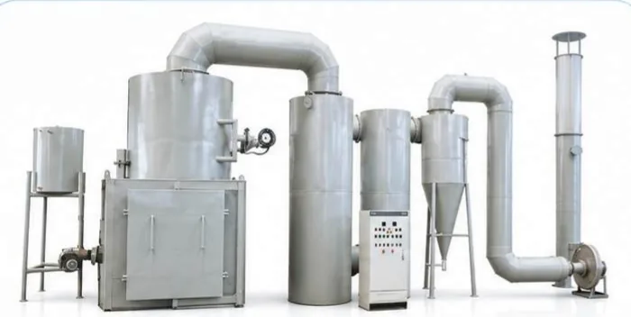
Choose the process and the site provision together
Compare the flue-gas configuration against the local limits, permit and project test plan. A waterless process does not by itself establish emission compliance.
| Configuration | Process water | Consumables and maintenance | Space and site provision |
|---|---|---|---|
| A · Dry purification chamber | No process water | Solid Ca(OH)₂ filter bricks; inspect and replace the media and remove collected residue. | Confirm access for media replacement. A does not include wet quenching, deacidification or activated-carbon towers, or the bag-filter combination. |
| B · Venturi wet combination | Water and pumps required | Inspect the wet-treatment units and water circuit; consumables and water management follow the final bill of materials. | Confirm water supply, pumps, drainage and maintenance access. The venturi scrubber, packed tower and cyclone dust collector are itemised in the project bill of materials. |
| C · Full wet combination | Water and pumps required | Quenching, deacidification, activated carbon, cyclone, bag filter, induced-draft fan and chimney; inspect the water circuit and replace consumables as specified. | Confirm the equipment layout, utilities, drainage and access for tower and filter maintenance. |
Emissions are set by the combustion stage and the flue-gas train
Emission performance is set by two things working together: the combustion stage and the flue-gas train. The secondary chamber at ≥850 °C with ≥2.0 s of residence time is designed to destroy organic compounds and oxidise carbon monoxide. Downstream, rapid cooling shortens the window in which dioxins and furans can re-form; a bag filter or cyclone captures particulate matter (PM) and the metals carried on it; activated carbon adsorbs dioxins, furans and mercury; and Ca(OH)₂ filter bricks or a wet deacidification tower neutralise acid gases. Nitrogen oxides in the standard supply are held at our design value of 350 mg/m³ by combustion control; the 300 / 250 mg/m³ national limit and the ≤200 mg/m³ limit both require a denitrification stage (SNCR or SCR), which is not part of the standard supply and is engineered per project. The configuration — A, B or C — is selected against the limit at your site, and the emission values are confirmed with that configuration rather than fixed in advance. These are design values, not a third-party test result; emission testing after installation is arranged by the site under its local rules.
| Incineration temperature | ≥850 °C |
|---|---|
| Flue-gas residence time | ≥2.0 s |
| Process temperature band | 800–1,200 °C |
| Nitrogen oxides (design value) | 350 mg/m³ as standard; the 300 / 250 mg/m³ national limit and ≤200 mg/m³ require a denitrification stage (SNCR or SCR) engineered per project, not part of the standard supply |
| Particulate matter, CO, dioxins and furans | Controlled by the stages above; values confirmed per project and configuration |
| Residue loss on ignition | ≤5 % in GB 18484-2020 Table 1 (hazardous waste); not a supplier test result |
| Operating voltage | 380 V or 220 V |
Design values, not third-party measurements. The applicable limit, test standard and configuration are agreed per project; installation-site emission testing is not part of the standard supply.
Applications
Hospitals and clinics
Infectious waste from wards, theatres and outpatient departments is treated on site, removing the transport step and the handling risk that comes with it.
Community and rural health facilities
Community health centres, outpatient stations and small private hospitals that have no scheduled hazardous-waste collection service can run their own daily disposal.
Laboratories
Cultures, contaminated consumables and expired reagents from medical and research laboratories are destroyed at source.
Remote and island facilities
Field hospitals, island clinics and sites far from a central treatment plant dispose of waste without depending on a collection chain.
Pharmaceutical and expired stock
Expired medicines and process waste that cannot leave the site untreated are destroyed in the same unit.
What is in the supply
Included
- Combustion chambers — primary chamber plus a secondary high-temperature stage; the CXMWI-200 uses four combustion chambers.
- Burner and combustion air — burner, combustion air blower and control valves.
- Control panel — unit-mounted controls for the burner and blower.
- Flue-gas treatment — configuration A: solid Ca(OH)₂ filter-brick purification chamber, no process water; configuration B: venturi scrubber, packed tower and cyclone dust collector; configuration C (full wet combination): quench, deacidification, activated carbon, bag filter and induced-draught fan. Nitrogen oxides in the standard supply are held at our design value of 350 mg/m³ by combustion control; the 300 / 250 mg/m³ national limit and the ≤200 mg/m³ limit require a denitrification stage (SNCR or SCR) engineered per project, which is not part of the standard supply.
- Export packing and documentation — factory assembled and tested before shipment, packed for export with the packing list, wiring diagram and operating manual.
Confirmed with your quotation
- Waste type and daily volume
- Emission standard and purification configuration
- Fuel — diesel, natural gas or LPG
- Site power, simple concrete foundation and stack arrangement
- Itemise the optional PLC, fuel tank and piping, short conveyor and other accessories in the quotation. Confirm the supply voltage, phases and frequency for the order. Temperature display/control, alarms, records and any interlock points follow the agreed control description and quotation; operation remains supervised.
- Shipping terms and delivery schedule
- Commissioning and operator training — arranged with the delivery schedule
- Site works, travel, trial run and acceptance responsibilities — stated in the quotation
- Third-party emission testing — not included in the supply; arranged by the site after installation
How the quotation is put together
A quotation is built from four items: the model selected for your daily volume, the flue-gas configuration that meets your emission standard, the fuel type available on site (diesel, natural gas or LPG), and the scope of transport and installation. These are confirmed with your proposal rather than fixed in advance.
Send your waste type and daily volume; we reply within 1 business day.
After-sales support
- One-year warranty on every unit.
- After-sales requests answered within 24 hours.
- Lifetime remote technical support for the equipment.
- A starter kit of spare wearing parts ships with every unit.
Installation and delivery
The CXMWI series is factory assembled and tested, then ships as separate modules — the combustion chambers, the purification chamber, the fuel tank, the chimney sections, the air duct and the burners — and bolts together on a prepared concrete foundation. A levelled slab, a lifting plan and the shipped fastener pack are the main site works. Assembly follows a fixed twelve-step sequence, and the first firing is a low-temperature preheating run before any waste is loaded. Commissioning and operator training are arranged with the delivery schedule.
- The shipment includes the packing list, wiring diagram and operating manual, and the delivery checklist covers every module, fastener set and spare, counted on arrival.
- Twelve assembly steps run from setting the primary chamber to the final bolt and valve check.
- The first firing preheats the furnace so moisture in the refractory evaporates before the first load.
- The quotation states the site works, travel, trial run and acceptance responsibilities; commissioning and operator training are arranged with the delivery schedule.
- The photoelectric cell, the fuse box and the fuel nozzle are site-replaceable spares shipped with the unit.
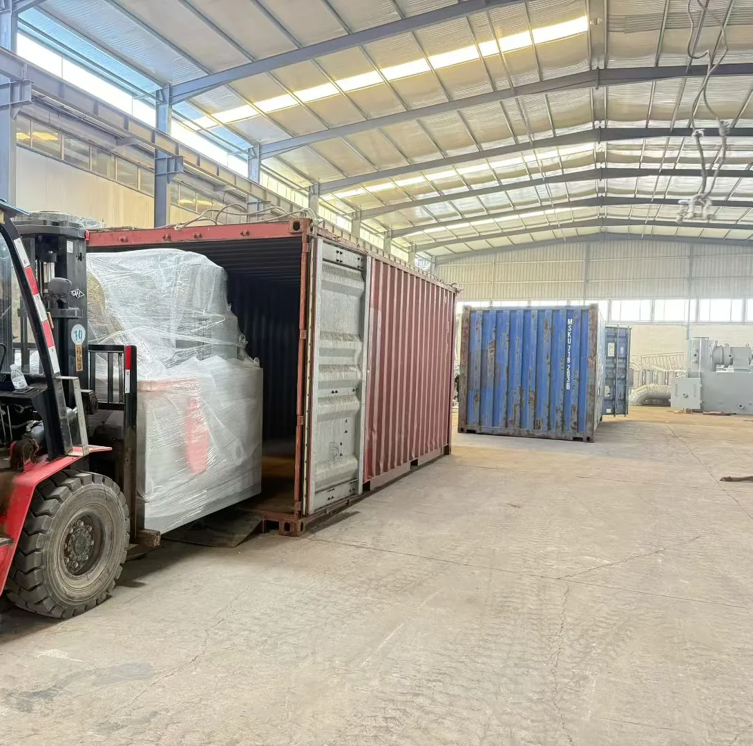
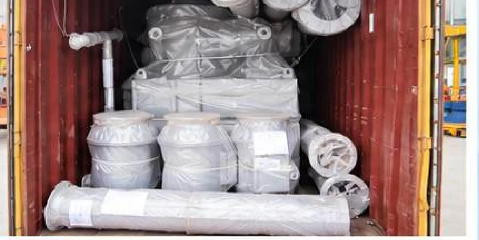
Factory manufacturing and burn-test reference
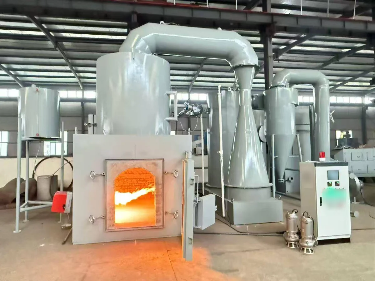
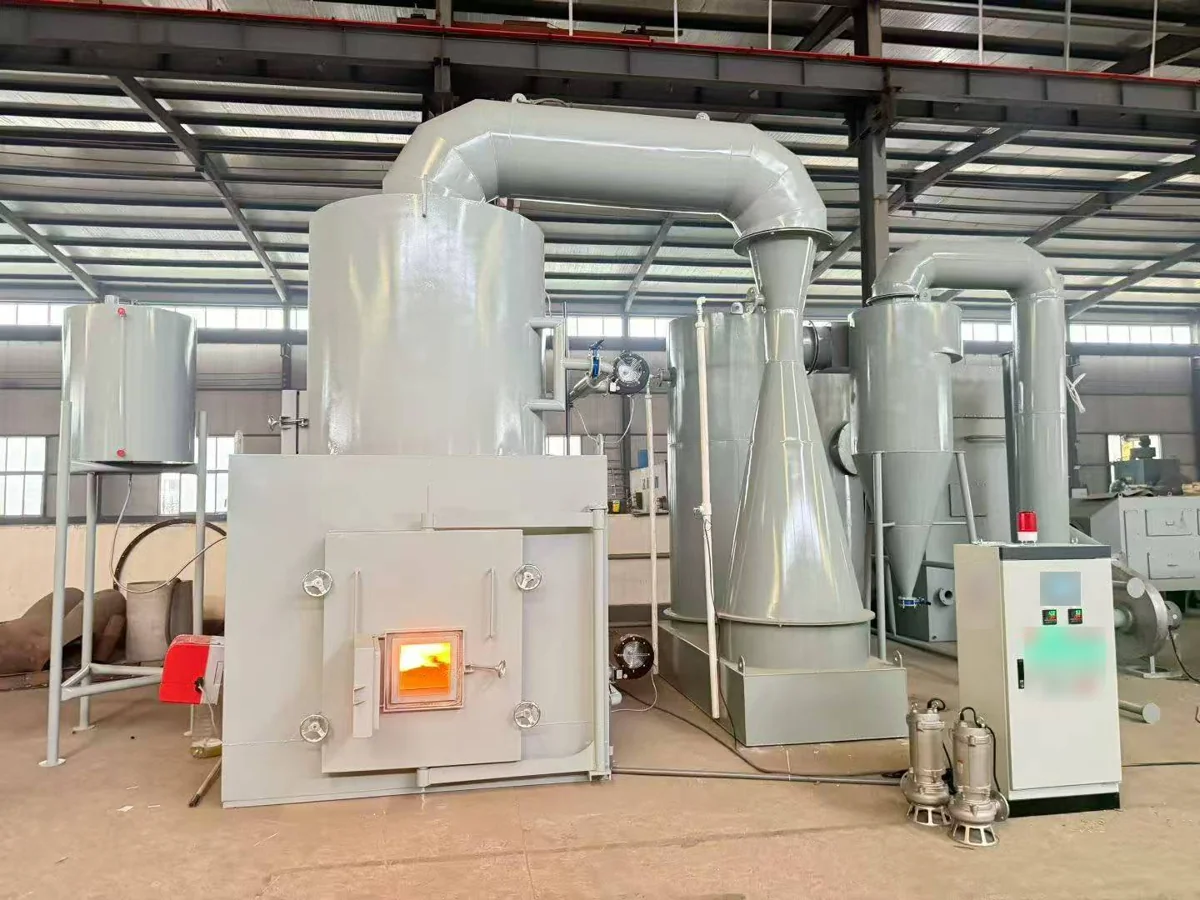
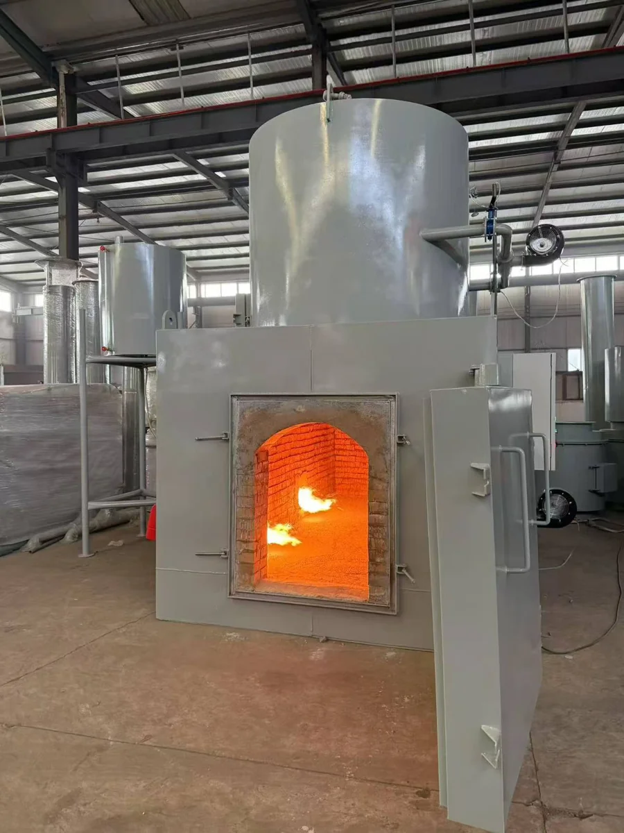
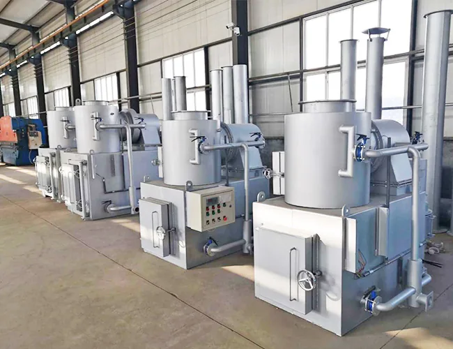
These photographs show a wet-configuration line and a furnace burn test. They do not depict the dry purification package or identify a project model; visible equipment does not define standard supply or prove emissions.
Selected projects
A selection of medical waste units delivered and commissioned since 2019, listed by country and year.
| Country / region | Waste type | Year |
|---|---|---|
| Zambia | Medical waste | 2019 |
| Congo | Medical waste | 2021 |
| Kuwait | Medical waste | 2022 |
| Philippines | Medical waste | 2023 |
| Mongolia | Medical waste | 2024 |
| China — Heilongjiang | Medical waste | 2024 |
Projects as recorded by our production department; customer names are not published. The model, capacity and emission configuration are set per project.
Medical waste destroyed where it is generated
Medical waste is hazardous from the moment it is generated: used syringes, dressings, expired medicines and contaminated disposables can carry infection, and holding them for collection lengthens exposure and adds transport risk. A medical waste incinerator destroys that waste at the point of generation. The waste is loaded into the primary chamber, and the gas passes into a secondary chamber at ≥850 °C with at least 2.0 s of residence time to complete the burn before it is cooled and cleaned. Volume is reduced by up to 90 % by volume, and the ash is collected and disposed of according to its character and local requirements. All CXMWI models are rated in kg/h, so the unit is matched to the daily output and operating hours rather than sold as one range.
Four stages from the flame to the chimney
The gas does not go straight from the flame to the stack. It passes through four stages, and their order is part of the design: each stage prepares the gas for the next.
- 1
Combustion
Waste burns in the primary chamber. The secondary chamber holds the gas at combustion temperature long enough to complete the burn before it leaves the furnace.
- 2
Cooling
In the wet configuration a quench tower cools the gas before it reaches the adsorbent. Cooling first keeps the adsorbent out of the hot gas and shortens the window in which dioxins can re-form.
- 3
Adsorption and dust removal
The flue gas is cooled and cleaned. Configuration A passes it through a Ca(OH)₂ filter-brick purification chamber with no process water; configuration B combines a venturi scrubber, packed tower and cyclone dust collector; configuration C adds quench cooling, deacidification, activated carbon adsorption and dust removal.
- 4
Induced draught and stack
In configuration A, Ca(OH)₂ filter bricks neutralise acid gases and adsorb pollutants, with no process water. Configuration C adds activated carbon and a bag filter after deacidification, and configuration B uses a venturi scrubber, packed tower and cyclone dust collector.
Combustion design figures for this range: incineration temperature ≥850 °C, flue-gas residence time ≥2.0 s, process temperature band 800–1,200 °C. The emission limits and the configuration that applies are confirmed against the regulation in force at the site.
Medical waste incinerator brochure
CXMWI model data, A/B/C flue-gas configurations, process-water needs, control and supply boundaries, and labelled factory-test photographs.
PDF · 10 pages · A4 · v2
Frequently asked questions
How do I choose a CXMWI model?
Start with the medical waste type and the amount produced each day. All CXMWI models are rated in kg/h, and the model table lists each hourly range. The final choice is confirmed against your daily volume, operating hours, loading pattern and emission standard.
What combustion conditions does it reach?
Published design figures for the range are an incineration temperature of at least 850 °C, a flue-gas residence time of at least 2.0 s and a process temperature band of 800–1,200 °C. Volume reduction is up to 90 % by volume. These are design values; emission values are confirmed with the flue-gas configuration selected for the site.
Do I need configuration A, B or C?
Configuration A uses a solid Ca(OH)₂ filter-brick purification chamber and needs no process water. Configuration B combines a venturi scrubber, packed tower and cyclone dust collector. Configuration C is the full wet combination: quench, deacidification, activated carbon, cyclone, bag filter, induced-draught fan and stack. A, B and C are the three flue-gas processes; the basic fuel series is a model and supply tier, not a further process. The configuration follows the emission standard that applies at your site.
Which control functions are included?
Itemise the optional PLC, fuel tank and piping, short conveyor and other accessories in the quotation. Confirm the supply voltage, phases and frequency for the order. Temperature display/control, alarms, records and any interlock points follow the agreed control description and quotation; operation remains supervised. Automatic cut-off on low temperature, combustion failure or a CEMS signal is not promised; required functions must be agreed for the project.
How are units delivered and commissioned?
Each unit is factory assembled and tested before shipment. The shipment includes the packing list, wiring diagram and operating manual. Commissioning and operator training are arranged with the delivery schedule, and the quotation states the site works, travel, trial run and acceptance responsibilities.
What certificates come with the incinerator?
The CE document for the listed incinerator models is an ICR Verification of Conformity under the Machinery Directive. ISO 9001 is our company management-system certificate. Neither is an emission test or proof of emission performance; see the two certificate entries linked below.
What fuel does the incinerator use?
The burner can run on diesel, natural gas or LPG, selected according to what is available at the site.
What does an incinerator cost, and what spares are needed?
We do not publish a price list. The price depends on the model, the flue-gas treatment configuration and the fuel. For running cost, the per-burner diesel input for each model is in the specification table; total fuel use depends on the waste calorific value, moisture, load pattern and local fuel price, so we do not quote a total figure. Wearing parts include burner parts, door seals and refractory sections, and the spare set shipped with the unit is listed in the offer. Send your waste type, daily volume and emission standard, and we will reply with a model and price within 1 business day.
Still have questions? Send them
Loading, model selection and delivery
How should I compare CXMWI hourly capacities?
Compare the published kg/h ranges directly, then check dimensions and weight by model. The same model suffix, such as “100”, does not by itself establish identical dimensions or weight. Confirm the final model against daily volume, operating hours and the project specification; the published CXMWI model table remains the selection reference.
Does a small hospital need automatic bin lifting?
For supervised operation with bagged waste weighing a few kilograms per bag, a short conveyor may assist loading after project review. Large bin lifts and continuous unattended feeding are not default requirements. Confirm waste packaging, loading frequency, combustion load and operator availability.
Which items belong in the supply list?
Itemise the optional PLC, fuel tank and piping, short conveyor and other accessories in the quotation. Confirm the supply voltage, phases and frequency for the order. Temperature display/control, alarms, records and any interlock points follow the agreed control description and quotation; operation remains supervised.
Is CEMS the same as a third-party emission test?
No. A continuous emission monitoring system and a third-party emission test have separate scopes. Monitoring-system procurement, installation assistance, commissioning and signal functions must be stated in the project list; no automatic cut-off from CEMS is promised here.
How are packing and unloading agreed?
Confirm the packing method and containers per unit in the packing plan. Site cables, unloading and other responsibilities follow the agreed scope and trade terms; neither a wooden crate nor one fixed container count is universal.
Related pages
Get a model and price for your site.
Tell us the waste type, daily volume and emission standard. We will recommend a CXMWI medical waste incinerator and reply with a configuration and price.
- Model selected from the published CXMWI medical waste capacities
- Flue-gas configuration A, B or C matched to your emission standard
- Reply within 1 business day
Your details are used only to answer this inquiry.
For a quotation, include daily operating hours, waste packaging and loading method, whether an operator is available, and the site water and power provision.