
Shallow air flotation.
A shallow-tank dissolved air flotation unit that separates suspended solids and oil in a short retention time, used as pretreatment ahead of a biological stage.
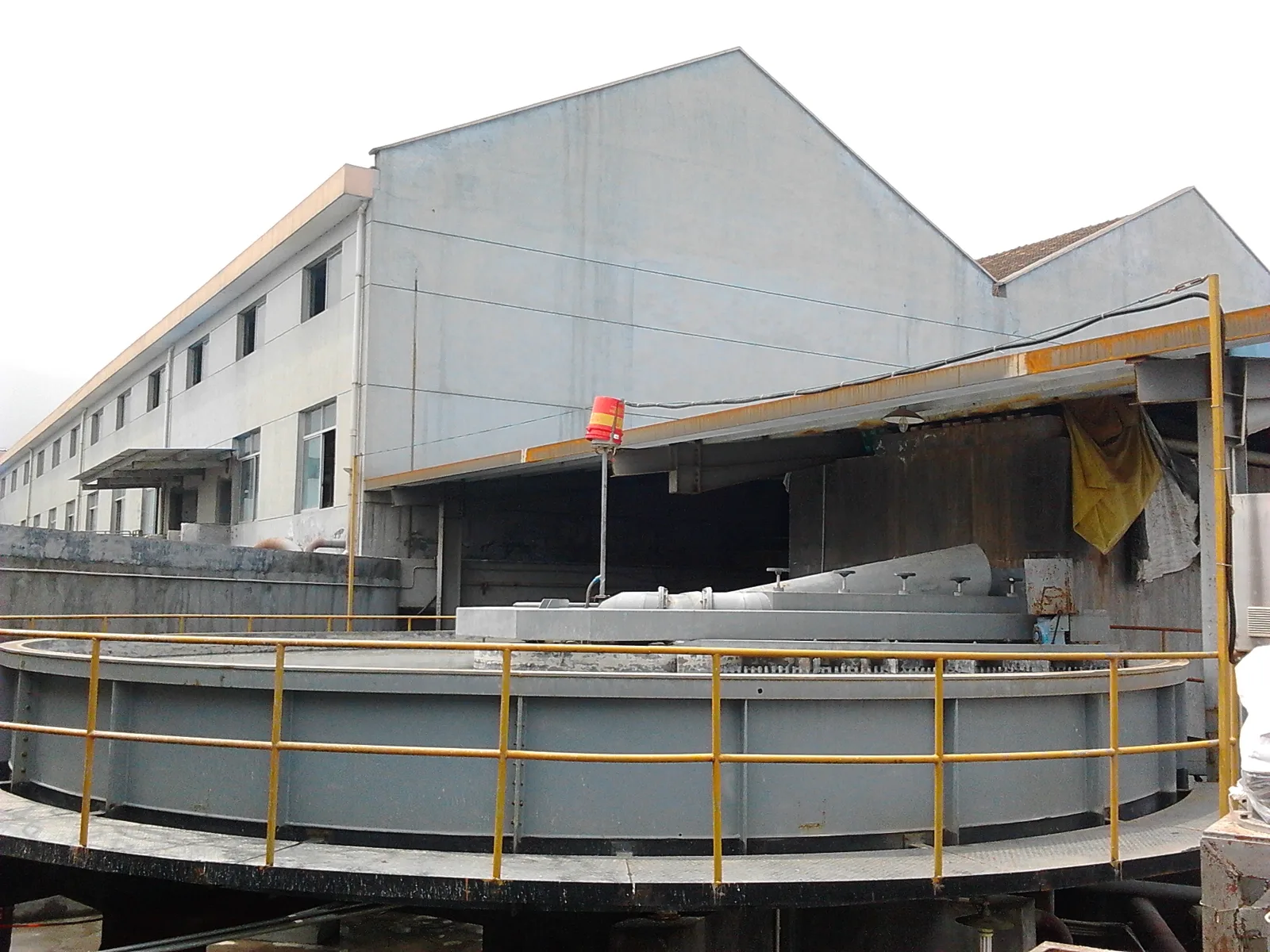
What a shallow air flotation unit is, and what the site still does
A shallow air flotation unit separates suspended solids, oil and grease by attaching them to bubbles in a tank that is deliberately shallow, and it is normally used as pretreatment ahead of a biological stage: it takes the solids and the oil out, so the biology behind it receives a steadier and cleaner feed. The shallow depth keeps the retention time short and the surface loading the tank can carry high, which is what makes the unit compact. The unit is assembled and tested at our factory, so on site only the prepared foundation, the placement, the inlet and outlet connections, the power feed to the control panel and the commissioning support remain.
The difference from the full-tank and horizontal-flow designs is geometry. The shallow unit is built as a round shallow basin with the influent, the dissolved-air release, the float collection and the sludge discharge arranged around it; the water level and the skimming depth are both adjustable, so the unit can be trimmed to the float that is actually produced. The shallow depth makes the float easy to collect, and the material that does not float is collected separately at the bottom.
That geometry has limits. Heavy grit and debris have to be screened out before the unit. Free oil that is worth recovering as a product belongs in an oil separator rather than in a flotation tank. A duty whose flow sits above the published range is met with more than one unit or with a different configuration, not by stretching the model. The dissolved air flotation family page sets the shallow configuration against the full-tank and horizontal-flow ranges. It is not a polishing step for dissolved matter, ammonia or soluble COD, and it is not a substitute for the biological stage it protects.
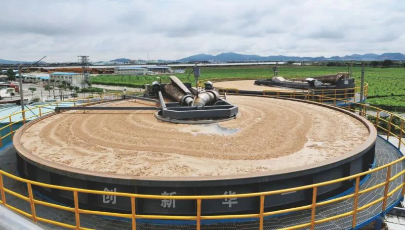
Capacity, disc area and the surface loading check
The CXQF table publishes the maximum capacity in cubic metres per day and the disc diameter in millimetres. The surface loading is the flow divided by the plan area: capacity in m³/d divided by 24 gives m³/h, the disc area is π/4 × diameter², and the surface loading is the flow over that area in m³/m²·h. Across the six published models that gives about 4.4–5 m³/m²·h.
Worked through on one model: CXQF-100 is 2200 m³/d, so 2200 ÷ 24 = 91.7 m³/h; its 5000 mm disc gives π/4 × 5.0² = 19.63 m²; and 91.7 ÷ 19.63 = 4.67 m³/m²·h. Those capacity and diameter values, and that formula, are the same ones the DAF sizing calculator uses, so the page figure and the calculator cannot drift apart.
What the table does and does not say
The capacity is a published maximum, not a promised duty for your stream. The actual area, recycle rate and chemical dose are confirmed at sizing from the flow, the solids load and the oil load. The surface loading and hydraulic loading article sets out the unit and the assumptions.
Float concentration and what happens to it
The skimmed float can be concentrated to about 35 percent under the stated duty. That is a catalogue reference, not a project result: the concentration depends on the feed solids, the chemical dose and the skimming depth, and it is confirmed on the actual stream. The float still has to be thickened or dewatered and sent to a legal outlet, which is a separate stage from the flotation unit.
The sludge dewatering range takes the float on to a handleable cake, and the final disposal route follows the local rule and the waste classification rather than a generic statement.
Supply, foundation, interfaces and transport
The unit is built as one item so that it can be installed on a prepared foundation. The commercial offer fixes the scope line between our supply and the site.
- In our supply — the shallow basin with its release, float collection and sludge discharge, the saturator package, the recycle pump, the air compressor, the skimming drive and the control panel.
- Your site work — the prepared foundation and drainage, the inlet and outlet pipework to the unit flanges, the power cable, the lifting and placement, and any chemical dosing station supplied separately.
- Transport — the transport envelope is confirmed with each order against the packed dimensions, the route and the port of discharge.
The unit is factory-tested, not a turnkey building. Installation is confirmed from the site layout and the foundation drawing, and the selection and sizing guide takes the site conditions into the choice.
Acceptance is written into the contract: factory acceptance tests before shipment, site acceptance tests after installation, and a performance test at design load, with the removal guarantee, the sampling point and the test method fixed for the project against the receiving works' standard. A failed result is rectified and retested as agreed. Acceptance records are project documents, not published specifications; when you compare quotations, ask for the acceptance section of the contract.
What the evidence for this configuration is
The model table on this page is catalogue data, not a first-party test on your stream. The capacity and diameter are published figures and can be recomputed as shown above; the removal and float concentration are catalogue references under the stated duty. First-party test data, installed power and the project drawings are confirmed with the factory for the duty, and the test conditions are what a quoted removal figure has to be read against.
- Published here — the CXQF model, maximum capacity, disc diameter and disc height from the catalogue, and the surface loading recomputed from them.
- Confirmed per project — the duty capacity, the recycle rate, the chemical dose and the installed power for the actual flow and load.
- Available on request — the factory test record, the outline and foundation drawings, the O&M manual and the spare-parts list.
- References — project cases only where the customer has agreed to be named.
The working-principle article explains what the bubble mechanism can deliver, and the family page carries the configuration comparison and the other two ranges.
CXQF super-efficiency shallow air flotation
The CXQF unit is a shallow-tank dissolved air flotation plant. The tank is built as a round shallow basin with the influent, the dissolved-air release, the skimmed float collection and the sludge discharge arranged around it; the water level and the skimming depth are both adjustable, which lets the unit be trimmed to the float that is actually being produced. The shallow tank keeps the float easy to collect and the retention time short, and the floor that does not float is collected separately. The unit is built as one item so that it can be installed on a prepared foundation, and the tank material and scraper arrangement are chosen against the water being treated.
| Model | Max capacity (m³/d) | Diameter (mm) | Total disc height (mm) |
|---|---|---|---|
| CXQF-65 | 1500 | 4000 | 1100 |
| CXQF-100 | 2200 | 5000 | 1100 |
| CXQF-200 | 4500 | 7000 | 1125 |
| CXQF-250 | 6000 | 8000 | 1150 |
| CXQF-320 | 7500 | 9000 | 1150 |
| CXQF-420 | 10000 | 11000 | 1200 |
Dimensions are reference values reproduced from the factory catalogue and are approximate. Final dimensions and weights are confirmed against the site conditions and the actual build.
Saturator, release and skimming equipment
A dissolved air flotation unit is only as good as the bubbles it makes. A pump charges air into the saturator vessel under pressure, the air dissolves into the recycle water, and the release device spreads that water across the tank so the bubbles form where the solids are. The saturator, the recycle pump and the air compressor are the parts that set how much air the unit can deliver, and they are selected together with the tank area so that the surface loading rate and the air-to-solids ratio suit the water. The skimming arrangement then has to take the float off at the rate it is produced without drawing water with it, which is what the adjustable skimming depth is for.