
Containerized sewage treatment plants, factory-assembled around your site and discharge target.
The treatment train is assembled, piped and wired in our factory, then shipped as a container-style unit. Your site provides the foundation, the external connections, the power and the support for commissioning.
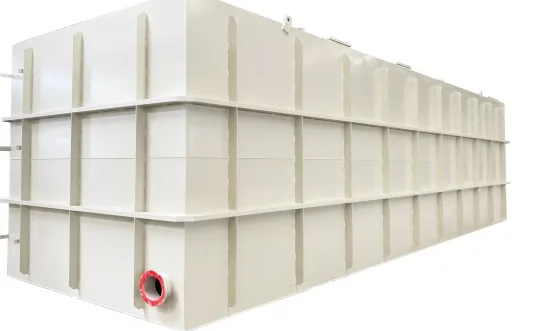
Assembly moves into the factory; the site only connects the unit
A containerized sewage treatment plant is the whole treatment train — assembly, pipework, wiring and a trial run — moved off the building site and into a factory. The unit arrives complete: you prepare the foundation, set it down, connect the inlet and outlet, bring power to the panel and support commissioning.
Package plant, packaged plant and containerized plant are three names for the same delivery model. They differ in how the unit ships, not in how the water is treated.
The enclosure is sized to the duty, not to a standard dry container. Smaller units ship closed; larger ones move on a flat rack, in an open top or as bulk, confirmed per order.
Why move treatment plant assembly into a factory?
In a conventional treatment project, the civil works and the cross-trade coordination stay on site. Basins are poured there; pumps, blowers, screens, membrane modules and control panels arrive as separate packages; pipework and cable trays are cut and fitted where they will stay; and each trade waits for the one before it, in the open, in whatever weather the site offers. Factory pre-assembly changes that division of work: we build the treatment train on a frame or inside a container-style enclosure, connect the internal pipework, mount the blowers, pumps and control panel, and test the assembly before it leaves. Your site then carries a smaller set of tasks: prepare a level foundation, bring the unit in and set it down, connect the inlet and outlet, bring power to the panel, and support commissioning.
What does not change is the treatment itself. Pre-assembly does not make a plant smaller, remove the need for biology, or replace the discharge standard. The same screening, equalization, biological treatment and disinfection steps still have to be sized for your wastewater. The factory changes where part of the work happens; it does not change how the water is treated.
Containerized or built on site: compare the whole project
The card above is where the conventional route hurts. This table is for the decisions it cannot settle: footprint, expansion, relocation, transport, large tankage and the skills your site still needs.
Wide table: scroll sideways to see every column.
| Question | Containerized, factory-assembled | Built on site, civil works |
|---|---|---|
| Layout and footprint | The unit occupies the transport envelope it was built in; the layout inside is fixed by the factory design | Basins can follow the available land shape, but the plant is fixed once poured |
| Expansion | Add a module or a parallel unit, subject to space and connections | Extend with new civil works, often while the plant is running |
| Relocation | Possible for the module, but transport, lifting and reconnection have to be planned again | Effectively permanent once the concrete has cured |
| Transport | The unit has to fit a transport route; oversize units need a project-specific method or a split design | Materials and equipment travel separately, so there is no single oversize lift |
| Large tankage | Steel tankage inside an enclosure becomes expensive as volume grows | Poured concrete can be the lower-cost way to hold large water volume |
| Site skills needed | A contractor who can prepare a pad, make connections and support commissioning | Local civil, mechanical and electrical trades, plus supervision across all three |
Comparing the whole project, not the equipment price.
The factory form is not automatically cheaper or faster. Its advantage is that a defined part of the work is done once, indoors, by the crew that built it, and inspected before it ships. Its cost is the enclosure and the transport envelope: a container-style unit pays for steel walls it would not need inside a building, and it has to be able to travel to the site.
The site-built form wins when water volume dominates the cost, when local labour and materials are cheap, when land is available and the programme is long, or when the plant will never move. It loses when the site has no contracting capacity, when the schedule cannot absorb a concrete programme, or when the plant may have to relocate.
A hybrid is another option, and often the efficient split: civil works for the basins where volume dominates, and factory-assembled equipment for the process stages that gain most from testing before delivery. The comparison of skid, container and civil works works through the same boundary conditions in more detail.
The container is the delivery form. The process still follows your wastewater.
The enclosure does not decide the process. Your influent and your discharge or reuse target do. What the factory assembles is a treatment chain, and each step exists for a reason that can be stated before any equipment is chosen.
- Screening and grit removal: coarse solids, grit and debris are taken out first, so that pumps, valves and downstream tanks are not asked to handle material they were not sized for.
- Equalization: flow and quality vary through the day, and a buffer volume lets the biological stage see a steadier feed instead of the peak the sewer delivers.
- Biological treatment: dissolved and suspended organic matter is removed by a biomass. A/O, MBBR and conventional activated sludge are different process arrangements, not interchangeable labels; the choice depends on the load, the nitrogen target, the footprint and the operator.
- Membrane separation: where the discharge or reuse target needs a finer solids barrier than settling can give, MBR adds membrane separation after biology. It is an option, not a default; the integrated MBR equipment page covers what an MBR package includes.
- Disinfection: the final step reduces pathogens before discharge or reuse, and the method follows the target and the downstream use.
- Discharge or reuse: the treated water leaves to a receiving water body, an irrigation system or a flushing supply, and the standard for that destination is what the whole chain is sized against.
The sequence is fixed during sizing, not before it. A plant with membrane separation is not an A/O plant with a membrane added as an afterthought, and an MBBR is not a smaller version of an activated sludge tank. The effluent standards chart shows how a discharge target narrows the process options, and the comparison of MBR, MBBR and SBR sets out where each arrangement fits and where it does not.
Start with your flow, then check the load and the site
Two loads decide the size of a treatment plant. The hydraulic load is the volume of water arriving per day; it sets the pipes, the tank volumes and the hours the plant runs. The organic load is the mass of pollution in that water; it sets the biology, the air demand and the sludge production. A plant sized on flow alone can be too small for a strong wastewater, and a plant sized on load alone can be too small for a wet day.
Site conditions sit alongside both. A level foundation, the space to bring the unit in and lift it, the distance to the inlet and outlet, the power available and the room to expand all constrain the model that can be used, before any process choice is made.
The CXWSZ series below is our catalogue range. It is a starting point for the hydraulic duty, not a fixed-scope offer: the final process, model, unit count and scope are confirmed against the influent, the discharge or reuse target, the site and the power supply.
Wide table: scroll sideways to see every column.
| Model | Capacity (m³/h) | Dimensions L × W × H (mm) | Units | Weight (t) | Air demand (m³/min) |
|---|---|---|---|---|---|
| CXWSZ-0.5 | 0.5 | 3000 × 1500 × 2000 | 1 | 1.5 | 0.13 |
| CXWSZ-1 | 1 | 4000 × 1500 × 2000 | 1 | 1.7 | 0.26 |
| CXWSZ-2 | 2 | 5000 × 2000 × 2000 | 1 | 2.5 | 0.52 |
| CXWSZ-3 | 3 | 7000 × 2000 × 2500 | 1 | 3.5 | 0.78 |
| CXWSZ-5 | 5 | 10000 × 2500 × 2500 | 1 | 4.5 | 1.3 |
| CXWSZ-10 | 10 | 16000 × 2500 × 2500 | 1 | 8.4 | 2.6 |
| CXWSZ-20 | 20 | 16000 × 2500 × 2500 | 2 | 16.8 | 5.2 |
CXWSZ catalogue range for the hydraulic duty.
Dimensions are reference outline dimensions and weights are approximate equipment weights. Both are confirmed against the actual build once the site conditions are known.
A flow figure alone does not describe the load. For early estimates we use the design assumptions below for domestic sewage. They are a starting envelope for arithmetic, not a measurement of your water.
Wide table: scroll sideways to see every column.
| Parameter | Preliminary design assumption |
|---|---|
| COD | 300–800 mg/L |
| BOD5 | 150–400 mg/L |
| TSS | 150–450 mg/L |
Preliminary design assumptions for domestic sewage — replace with your test results.
Preliminary design assumptions, not a specification
These values are used only for early estimates and must be replaced with your own test results. They are not a reference for industrial wastewater, not a guaranteed influent range for our equipment and not a guaranteed effluent value.
Convert the design flow and the concentration into the numbers the process needs. Qd is the design flow in m³/day and C is the concentration in mg/L.
- Average hourly flow: Qh = Qd / 24
- Daily load: kg/day = Qd × C / 1000
- Daily load to remove: kg/day = Qd × (Cin − Cout) / 1000
Worked example, not a project case
Take Qd = 120 m³/day, COD = 500 mg/L, BOD5 = 250 mg/L and TSS = 250 mg/L. The average hourly flow is 120 / 24 = 5 m³/h. The daily loads are 120 × 500 / 1000 = 60 kg/day COD, 120 × 250 / 1000 = 30 kg/day BOD5 and 120 × 250 / 1000 = 30 kg/day TSS.
CXWSZ-5 matches the 5 m³/h hydraulic figure, so it is a hydraulic starting point for this example. It is not a selected plant: the peak flow, the organic load, the discharge or reuse target and the site still have to be checked, and the model may change once they are. The selection and sizing guide lists the site data we need to turn it into a configuration.
Reference treatment performance for a contact-oxidation design
Reference basis, not measured performance
The table below is a published contact-oxidation design reference taken from an external public catalogue. It is not measured performance of our equipment and not a guaranteed effluent value. Actual effluent is confirmed for each project against the selected process, the influent, the destination country discharge or reuse standard and the test method.
The reference values below are public design guidance, not an acceptance result; your performance test is what proves the plant.
Wide table: scroll sideways to see every column.
| Parameter | Influent reference (mg/L) | Reference effluent (mg/L) | Calculated reduction |
|---|---|---|---|
| COD | 200–400 | 70 | 65–82.5% |
| BOD5 | 100–200 | 20 | 80–90% |
| TSS | 200–450 | 30 | 85–93.3% |
Calculated from the reference endpoints.
- Removal efficiency = (Cin − Cout) / Cin × 100%
Use the table as a worked reference, not as a selection rule. Put your own influent concentration and the effluent target that applies at your site into the formula; the result tells you what the process has to achieve, not what this design will deliver. Our project configuration and effluent values are fixed against the destination country standard and its test method. The table does not replace the project design.
Where our supply ends and your site work begins
A factory-assembled plant is not a plug-in appliance. The boundary between our supply and your site work belongs in the order, and it is worth writing down before the unit is built.
Wide table: scroll sideways to see every column.
| Scope | Our factory supply | Your site work |
|---|---|---|
| Assembly and internal piping | Treatment train assembled, internally piped and mounted in the enclosure or frame | Receive the unit, set it on the foundation and make the external connections |
| Electrical and control | Control panel, internal wiring and the interface points for site power | Supply power to the panel at the agreed voltage, phase and frequency; external cabling |
| Documented scope | Unit drawings, internal layout and the agreed interface list | Confirm the interface list against the site before shipment |
| Foundation and civil | No civil work is included inside the unit | Level foundation or pad, drainage and any bund required by the site |
| External piping | Inlet and outlet connection points on the unit | Inlet and outlet piping to the unit, and the connection to the receiving works |
| Power supply | Equipment configured for the voltage, phase and frequency of the destination country | The supply itself, its protection and its earthing |
| Unloading and lifting | Lifting points and the shipping arrangement agreed with the order | Crane or forklift capacity, access for the transport vehicle and a safe lifting plan |
| Commissioning | Mechanical checks, control checks and commissioning support | Site utilities, operator availability and the samples needed to start biological commissioning |
The supply boundary, agreed before the unit is built.
Power is matched to the destination, not assumed. We configure the plant for the voltage, phase and frequency of the country it is going to; a 60 Hz site needs motors, drives and a control panel matched to 60 Hz, because frequency cannot be corrected with a transformer. The nameplate values are fixed with the order, not taken from a catalogue range.
Mechanical installation and biological commissioning are separate events. Mechanical completion means the unit is set, connected and the equipment runs. Biological commissioning means the biomass is established and the plant is brought up to its design duty. They are planned as two stages, and the time each takes depends on the site, the wastewater and the operator. We do not quote a single number of days for both.
Packing and dispatch examples from our factory. These photographs come from several dispatch batches; the transport arrangement is confirmed per order and does not imply that every unit travels the same way.
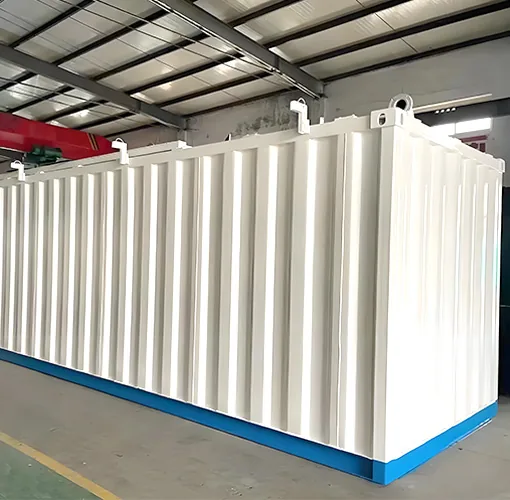
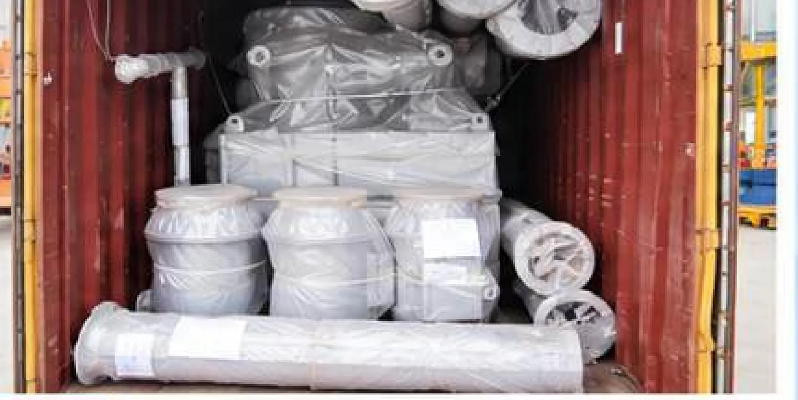
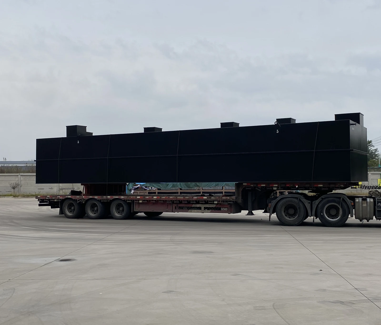
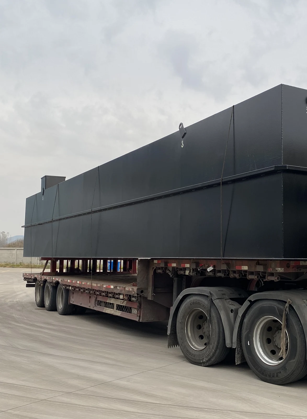
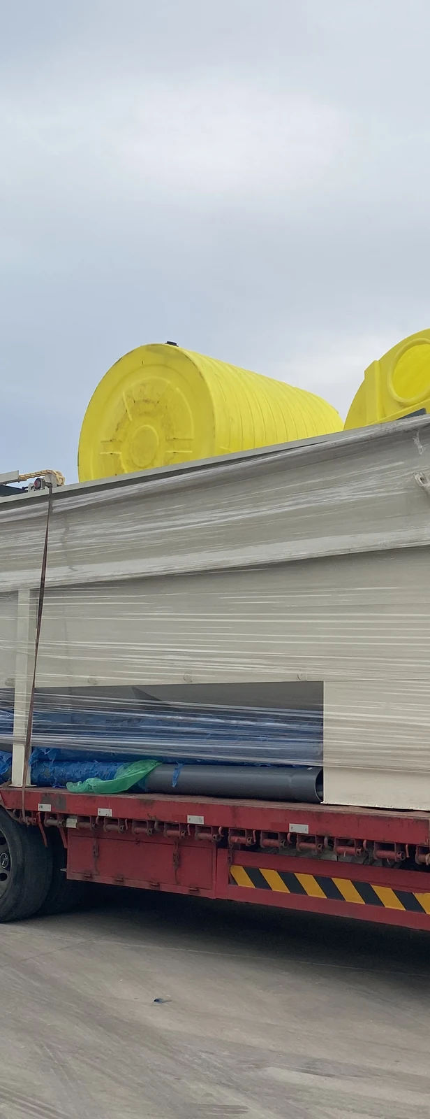
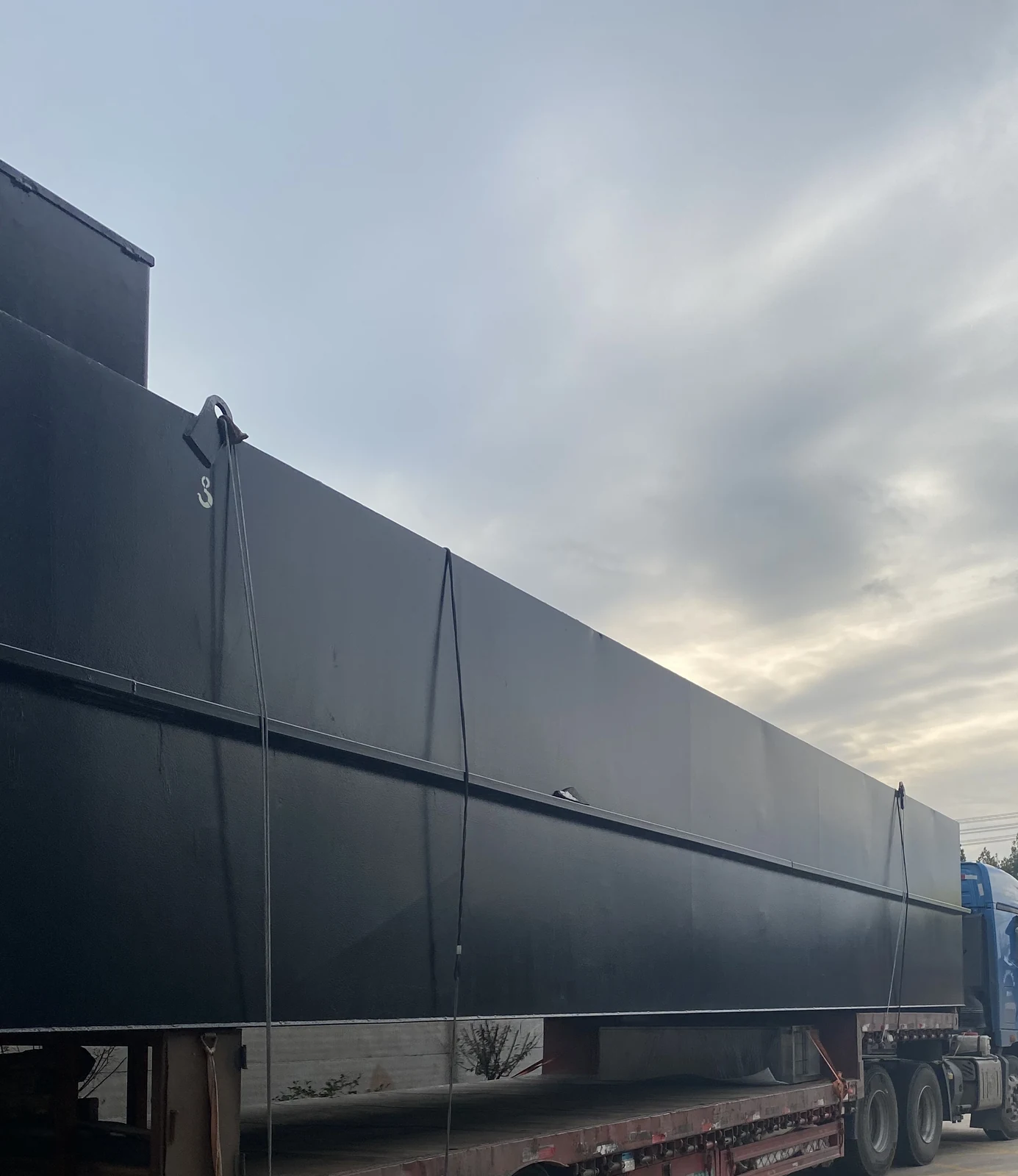
The words containerized and container-style enclosure describe how the unit is built, not a promise that it travels inside a standard dry container. A 40 ft dry container is about 12.03 m long and 2.35 m wide inside. The CXWSZ-10 outline in the table is 16 × 2.5 × 2.5 m, so it cannot be described as an ISO container or as fitting a dry container. Units larger than the transport envelope need a project-specific transport method or a split design, agreed with us before the order. What fits in a shipping container explains the envelope, and commissioning and operating a packaged plant covers the site phase after delivery.
Acceptance is written into the contract: factory acceptance tests before shipment, site acceptance tests after installation, and a performance test at design load. The standards and test methods are fixed with your influent and discharge target before manufacture. A failed result is rectified and retested as agreed.
Acceptance records are project documents, not fixed specifications; when you compare quotations, ask for the acceptance section of the contract.
Who runs the plant, and what handover includes
A packaged plant still needs a person who understands what the readings mean. The handover is planned with that person in mind: an operating manual for the delivered configuration, a walk-through of the daily and weekly checks, training on the control panel and the alarm response, a spare-parts list for the items that wear, and a route for remote support when a fault is outside the site team experience.
The scope is confirmed per project rather than assumed. Operator numbers, the training format, the language of the manual and the spare-parts holding are written into the order, because a plant on a remote island and a plant beside a staffed works need different handover arrangements. We ask for the operator profile at sizing and match the instrumentation and the documentation to it.
The running cost has four parts: aeration energy, because the blowers run whenever the biology is working; sludge handling, because surplus sludge has to be dewatered and taken away; membrane replacement on a membrane plant; and the chemicals used for disinfection and, where required, phosphorus removal. We do not publish a cost figure, because the tariff, the load and the local disposal route decide it; the four parts are what a project budget has to carry.
What leaves the plant besides treated water
Treatment separates material from water, and that material has to go somewhere. Screening removes coarse solids and debris; grit removal takes sand and dense particles; the biological stage produces surplus sludge; and a membrane plant produces a concentrate or rejection stream where cleaning or a separation duty is part of the process. Each is a separate waste with its own handling and disposal route.
Our scope covers the equipment that collects and, where specified, dewaters these streams. The legal disposal route belongs to the project: it depends on the waste classification, the local rules and the contractor licensed to take it. The screening and grit quantities, the sludge volume and the dewatering target are confirmed with your site data before the order; we do not quote a disposal volume from a catalogue.
Disposal responsibility is written down, not assumed
The order states which residual streams our supply collects and treats, and which disposal steps your site or its contractor carries. The local rule that classifies the sludge and the screenings is confirmed for the project, because it decides the permitted route.
Power, utilities and what happens when the supply stops
Power is matched to the destination, not assumed. We configure the motors, drives and control panel for the voltage, phase and frequency of the site, because frequency cannot be corrected with a transformer. The nameplate values and the connected load are fixed with the order from your electrical data; they are not taken from a catalogue range, and this page does not publish a power figure without a specific project.
A stop in the supply is a process event, not only an electrical one. Aeration stops, the biology begins to consume the oxygen in the tank, and a long outage can change the sludge. The control philosophy agreed for the plant sets what happens on restart: whether the blowers and transfer pumps restart automatically, what alarm reaches the operator, and what the site has to check before the plant is returned to duty. Battery backup, a standby generator or a manual restart procedure are project options, confirmed against the site supply and the acceptable outage.
The other utilities are small but real: water for cleaning and for the commissioning fill, air for any pneumatic valve or instrument, and the chemicals for disinfection and phosphorus removal where those steps are fitted. Each is listed in the interface schedule that goes with the order.
Drawings, records and the project case file
The document set is part of the delivery. For the agreed scope it includes the outline and interface drawings, the operating manual for the delivered configuration, the control and alarm list, the spare-parts list, and the FAT and SAT records once those tests are done. Certificates and test reports are listed only where the document exists for the project and the destination market; we do not attach a certificate mark to a page to imply a scope it does not cover.
Project references are handled the same way. We can describe a project only where the customer has authorised the reference and the result can be documented; a photograph of a unit on a flatbed proves the delivery, not the performance. Ask for the reference list and the document set that applies to your market, and check that the two agree.
Bring your site conditions into the comparison
By the time the delivery form is compared, the project usually has enough information to settle most of it. Bring these conditions into the same conversation:
- Design flow and peak factor: average flow sets the daily load, and the peak sets the pipes and the buffer volume.
- Influent quality: COD, BOD5, TSS, nitrogen and any industrial contribution, from a sample taken at the point and time that decide the duty.
- Discharge or reuse target: the standard, the receiving water body or the reuse application, because it decides the process train and the disinfection step.
- Site construction capability: local contractors, concrete supply and supervision, or the absence of them.
- Expansion and relocation: whether the plant may grow or move, and what that is worth paying for now.
- Transport and lifting: the largest piece against the route, the crane and the access.
- Power: voltage, phase and frequency together, not voltage alone.
With those conditions on the table, the comparison becomes a project decision rather than a product preference. If you send them with the enquiry, we return a sized configuration and a scope boundary; the price follows the scope, not a catalogue range.
Related pages
Get a configuration and quotation for your project
Share what you know about the wastewater, flow and project location. We will review the information and confirm what else is needed for a quotation. You can leave details blank if they are not yet known.