
Sewage pump stations, sized from the duty point and the wet well.
Pumps, pipework and controls built into one prefabricated chamber — assembled and trial-run at our factory, then lowered into the excavation and connected on site.
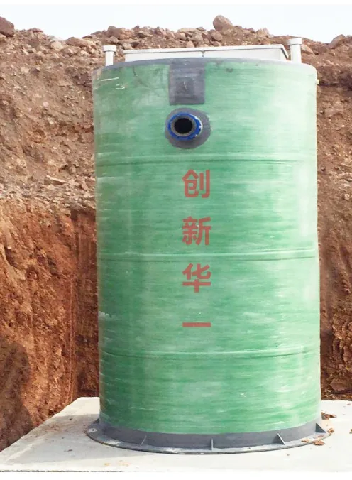
What an integrated pump station is, and what the site still does
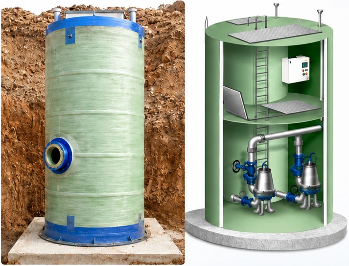
An integrated pump station lifts wastewater, stormwater or process water from a point where gravity can no longer carry it. The chamber is prefabricated rather than built in place: the shell, the submersible pumps, the guide rails, the internal pipework and valves, the level instruments and the control panel are assembled and trial-run at our factory, and the chamber arrives as one unit. The shell is offered in glass-reinforced plastic or carbon steel to suit the duty and the ground conditions, and the internals are arranged around the flow the station has to meet. On site the work is the excavation and dewatering, the base and the anti-flotation restraint, the backfill, the lifting and placing of the chamber, the connection of the inlet and outlet pipework to the chamber and the power cable to the control panel.
The duty point: where the pump curve meets the system curve
A pump station is bought on a duty point, and a duty point is two curves crossing. One is the system curve: the head the station has to produce at each flow, built from the static lift, the friction in the rising main, the minor losses and the velocity head at the outlet. The other is the pump curve: the head the selected pump produces at each flow, taken from its datasheet. The duty point is the flow and head where the two curves cross. A capacity figure without both curves is not yet a duty point.
- H = Hstatic + hf + hminor + hv (all in metres)
- hf = 10.67 × L × Q^1.852 ÷ (C^1.852 × D^4.87) (Hazen–Williams; Q in m³/s, D in m)
- hv = v² ÷ (2 × g), with v = Q ÷ (π/4 × D²)
- Inputs that belong to the project: static lift, pipe length, pipe material (C), fittings allowance, design flow.
Worked example, an engineering estimate rather than a measurement: a design peak inflow of 30 m³/h, a DN100 rising main 120 m long with C = 140, static lift 5.0 m, and minor losses taken as 20 percent of the friction loss. The velocity head follows from the same flow and pipe diameter. The table gives the system curve at three flows, up to 54 m³/h, so that it can be read against the pump curve.
Wide table: scroll sideways to see every column.
| Flow (m³/h) | Friction loss (m) | Minor losses (m) | Velocity head (m) | Static lift (m) | System head (m) |
|---|---|---|---|---|---|
| 18 | 0.55 | 0.11 | 0.02 | 5.0 | 5.7 |
| 36 | 1.99 | 0.40 | 0.08 | 5.0 | 7.5 |
| 54 | 4.22 | 0.84 | 0.19 | 5.0 | 10.2 |
System curve for the worked example. Engineering estimate from the stated inputs, not a measured head.
The duty point is then read where the Q-H curve of the selected pump crosses this system curve. The pump curve, its efficiency and the motor rating come with the pump datasheet for the project: this page does not publish a curve for a pump that has not been selected, and it does not promise that a particular pump will sit on the head of the example. When a station is ordered on these numbers, the pump is selected against the same system curve, and the NPSH margin, the solids passage and the motor rating are checked in the same step.
What this estimate is not
It is not a pump selection, not a guarantee of head at a given flow, and not a measurement. A project duty point needs the survey levels, the rising-main route and the pump datasheet, and all three are confirmed before the order.
Wet-well sizing: effective volume and starts per hour
The wet well absorbs the difference between what arrives and what the pumps take away. The volume that does the work is the effective volume between the pump start level and the pump stop level. Water below the stop level exists to keep the pump submerged, and the space above the high-level alarm is margin; neither counts as buffer.
A cycle is one fill and one draw. With an inflow Qin below the pump capacity Qp, the fill takes V ÷ Qin and the draw takes V ÷ (Qp − Qin). The shortest cycle, and so the highest starting rate, happens when the inflow is half the pump capacity, which gives the working rule below.
- V = Qp ÷ (4 × N) (V in m³, Qp in m³/h, N = maximum starts per hour)
- t cycle = 60 × (V ÷ Qin + V ÷ (Qp − Qin)) (minutes)
Worked example, an engineering estimate on the same basis: two pumps, one duty and one standby, each 36 m³/h at the duty point, with six starts per hour allowed by the motor. The design peak inflow is 30 m³/h, so one duty pump draws the well down even at the peak, and the standby cuts in on a high level or on a pump failure. The effective volume is 36 ÷ (4 × 6) = 1.5 m³, and the table gives the cycle at four inflows.
Wide table: scroll sideways to see every column.
| Inflow (m³/h) | Fill time (min) | Draw time (min) | Cycle (min) | Starts per hour |
|---|---|---|---|---|
| 9 | 10.0 | 3.3 | 13.3 | 4.5 |
| 12 | 7.5 | 3.8 | 11.3 | 5.3 |
| 18 | 5.0 | 5.0 | 10.0 | 6.0 |
| 24 | 3.8 | 7.5 | 11.3 | 5.3 |
Cycle time for the worked example at four inflows. Engineering estimate; the pump motor sets the allowed starts per hour.
The chamber size follows from the volume and the plan area. In the example the chamber is DN1400 from the table below: its plan area is π/4 × 1.4² = 1.54 m², so 1.5 m³ of effective volume is 0.97 m of working depth. The chamber height then has to cover the submergence below the stop level and the alarm margin above the start level; the pump datasheet sets the submergence, and the check is made before the chamber height is fixed.
The inflow to size on is the shortest peak the station has to pass, not an annual average. The peaking factor chart gives the factor for an average daily flow, the peaking factor calculator applies the same table to a flow or to a population and an allowance, and the population-to-capacity chart carries population through to a flow. Where the peak arrives faster than the wet well can cycle, the buffer belongs upstream: equalization tank sizing for peak flow sets out how that volume is read from a flow record.
Estimate, not a tested volume
Every volume and cycle time here is an engineering estimate from the stated inputs. The station is sized on the project flow record and the selected pump curve, not on this example.
Level control, alarms and standby changeover
Level control sets when a pump starts and when it stops. A float switch, a pressure transducer or an ultrasonic sensor can each provide the signal. The choice depends on the solids and grease in the flow, foam on the surface, the chamber shape and how much the site wants to see remotely; none of the three suits every station.
Two pumps are run as a pair, a lead pump and a lag pump, with the lead and lag roles swapped on a timer or after a set number of starts so that wear is shared. A pump that fails to start, or a level that keeps rising while a pump runs, brings the standby pump in on the high-level signal. The high-level alarm and a low-level cut-out are set outside the normal control band, so a control failure shows up as an alarm before it becomes a spill.
Where the signal goes is a site decision. A local lamp and horn is the minimum; a telemetry or dialler route to a control room or a phone is an option that has to be designed with the panel, not added afterwards.
Confirmed with the electrical design
The sensor type, the control levels, the alarm set points, the rotation interval and the remote-signalling route are written into the electrical design for the station. This page sets out the options; it does not publish one catalogue panel for every project.
Chamber, material and standby: what the choice depends on
The CXBZ table below gives a starting envelope: chamber diameter, chamber height, design inflow and pump count for the small and medium/large range. Read it as a catalogue reference, not a performance guarantee. The inflow column is the design inflow of the station, the pump count is a standby arrangement rather than a redundancy promise, and each project is confirmed against the actual build.
The shell is offered in glass-reinforced plastic or carbon steel. The choice turns on the ground and the groundwater, the depth of the excavation, the traffic loading over the cover, the corrosion exposure and the weight that can be lifted on site. Neither material is the universal answer, and the structural design for the project decides.
When a packaged station is the wrong choice: a flow beyond the largest chamber in the table, a site that wants the pumps in a separate dry well, a flow carrying debris that has to be screened before it reaches a pump, or a route that makes the static lift too high for a submersible arrangement. In those cases a cast-in-place wet well or a different lift point is the better answer. The plant selection and sizing guide takes the flow and the levels through that decision, and grit removal in wastewater treatment covers what has to come out of the flow before a pump sees it.
Where our supply ends and your site work begins
The station is factory-assembled and trial-run before shipment. What is in our supply and what stays on site is fixed in the commercial offer, and that split is what the project plan has to carry.
- In our supply — the chamber, the submersible pumps, the guide rails and lifting chain, the internal pipework and valves, the level instruments and the control panel, assembled and trial-run at our factory.
- Your site work — the excavation and dewatering, the base and the anti-flotation restraint, the backfill, the inlet and outlet pipework to the chamber, the power cable to the control panel, and the lifting and placing of the chamber.
- Fixed in the offer — the scope line, the interface list and any item supplied by a nominated vendor are stated in the offer, not left to the site to discover.
The station is not a turnkey building. The commissioning check is that the station runs, that the levels start and stop the pumps in the right order and that the alarm reaches its destination. A performance acceptance against a guaranteed duty belongs in the contract and is carried out on site at the flow and head the contract defines.
Power supply, starting and loss of supply
The motor voltage and frequency follow the site supply. They are recorded on the pump datasheet for the order; they are not assumed from a catalogue, and a station built for one supply is not re-rated for another on site.
The starting method is chosen from the motor rating, the supply capacity and the starting current the utility allows: direct-on-line for small motors, a soft starter or a variable frequency drive where the supply or the pipework cannot take the surge. A drive also lets the pump follow the inflow instead of cycling on level, at the cost of a harmonic and cooling question that belongs in the electrical design.
On loss of supply the pumps stop and the level rises. The high-level alarm has to reach someone who can act, and the response — a standby supply, emergency storage or a controlled overflow point — is a project decision. The station is not sold with a guarantee against overflow.
Installation, lifting and maintenance access
The chamber is set on a prepared base in a dewatered excavation and backfilled against the pipework and the shell. Where groundwater is present, the anti-flotation check compares the buoyancy of the empty chamber with its weight and its restraint. It belongs to the foundation design and is done before the chamber is ordered, not after it floats.
- Lifting — the chamber is lifted on the points marked for it, with the spreader and slings sized for the assembled weight.
- Connection — the inlet and outlet pipework connect at the levels shown on the chamber drawing, with flexible joints where settlement is expected.
- Access — guide rails and a lifting chain let a pump be raised for service from above, and valves and hatches are placed to be reachable without entering the chamber.
- Confined space — a wet well is a confined space. Entry follows the site permit, with a gas test, ventilation and a standby person, and the design should let routine pump work happen without entry.
Maintenance intervals follow the pump and the duty. The pump manual sets them, and the O&M plan for the station collects them in one place. Power and site conditions for export sets out the supply and site questions that arrive with a station shipped abroad.
What is issued with the station
These documents are issued with the station, for the pump and the chamber that were built:
- the pump datasheet, with the Q-H curve, the efficiency curve and the motor rating for the selected pump;
- the chamber drawing, with the dimensions, the inlet and outlet levels and the lifting points;
- the control logic and the wiring diagram for the panel as built;
- the O&M manual and the spare-parts list;
- the factory assembly and trial-run record.
We do not publish a sample Q-H curve on this page. A curve from a different pump would say nothing about the station you would receive, and a curve is only meaningful together with the pump it belongs to. Public references are limited to projects where the customer has agreed to be named; the documents for a specific station come with the enquiry.
CXBZ integrated pump station
The station is specified from the inflow it has to carry and the head it has to lift. Chamber diameter and height set the volume available for pumping and for the rising main, and the number of pumps sets the standby arrangement: a small station runs one or two pumps and a medium or large station two to four, so that pumps can be rotated and one taken out for service without interrupting the flow. The inflow column is a design inflow, not a tested capacity; the pump count is a standby arrangement rather than a redundancy promise; and both are confirmed against the duty point and the wet-well volume above.
| Station type | Chamber diameter (mm) | Inflow (m³/day) | Chamber height (m) | Pumps (units) |
|---|---|---|---|---|
| Small | 1200 | ≤1000 | ≤1.2 | 1–2 |
| Small | 1400 | ≤2000 | ≤6 | 1–2 |
| Small | 1600 | ≤6000 | ≤12 | 1–2 |
| Medium/large | 2000 | ≤10000 | ≤12 | 2–3 |
| Medium/large | 3000 | ≤35000 | ≤12 | 2–4 |
| Medium/large | 3800 | ≤86000 | ≤12 | 2–4 |
| Medium/large | custom | ≤100000 | ≤12 | 2–4 |
| Medium/large | custom | ≤120000 | ≤16 | 2–4 |
Values are our standard table; each project is confirmed against the actual build. The table is a catalogue reference, not a performance guarantee.