
Integrated MBR equipment.
Biological treatment and membrane separation in one packaged plant — compact, reuse-ready and assembled as a complete unit for site connection and commissioning.
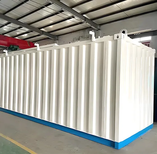
What an MBR is, and what the site still does
A membrane bioreactor is biological treatment and membrane separation built as one packaged plant. The biology removes organic matter and nitrogen; the membrane holds back the solids and pathogens that would otherwise carry over into the effluent, so the plant stays compact and the water is ready for discharge or reuse. The unit is assembled and tested in our workshop, so on site only the foundation, the placement, the inlet and outlet connections, the power feed to the control panel and the commissioning support remain.
The membrane is part of the packaged supply unless the offer names a nominated vendor; the module make, its design flux and the membrane area are fixed during design and issued with the order, not read off the model number.
It is not the right answer to every wastewater. A membrane is a barrier, and a barrier is damaged by what reaches it: free oil and grease, solvents, high suspended solids, sharp debris and substances that blind or attack the module all have to be removed or controlled before the membrane. Where the discharge standard is loose, land is available and the operator is thin, a conventional train or an MBBR can be the better value; the containerized sewage treatment plant is that alternative where membrane separation is not required.
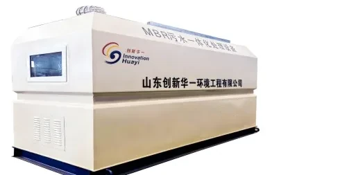
The membrane: who supplies it, how it is sized and when it is replaced
The membrane decides both the effluent quality and a large share of the running cost, so its boundary has to be explicit. The module make and model are confirmed with the membrane supplier at the order stage. The module is supplied with the packaged unit as part of our scope, and the commercial offer states whether a nominated membrane vendor is used instead. We do not put one catalogue membrane across the series, because the right module depends on the duty.
Design flux and membrane area are process-design outputs, not catalogue constants. They are calculated from the design flow, the peak flow, the mixed liquor concentration and the fouling load, and they are issued in the project design documents. The membrane datasheet, the design flux and the membrane area are confirmed with the order; none of them is inferred from the model number alone. The mechanisms behind fouling are set out in the four mechanisms of membrane fouling, and the cleaning routine in membrane cleaning chemicals and frequency.
Cleaning and replacement follow the membrane supplier guidance rather than a fixed calendar on this page. A maintenance clean is set by the operating regime; a recovery clean uses the chemicals the supplier specifies; and the replacement interval depends on the fouling load and on how well the pre-treatment and the biology are kept in balance. The cleaning regime, the chemical list and the expected replacement interval are written into the O&M plan for the delivered module.
Start with the flow, then check the load and the wastewater
Design flow alone does not size an MBR. The design needs the average flow, the peak flow and the peak factor, the organic and nitrogen load, the mixed liquor concentration the biology will run at, the wastewater temperature and the oil, grease and toxic load. Two plants with the same cubic metres per day can need different membrane areas and different tank volumes.
- Flow — average design flow and peak flow, with the peak factor stated rather than assumed.
- Load — COD, BOD, nitrogen and phosphorus, expressed as a daily load and not only as a concentration.
- Biology — the mixed liquor concentration is confirmed per project; it is not a single catalogue value across the series.
- Wastewater — temperature range, oil and grease, solvents, salinity and any toxic or inhibitory stream.
What does not suit a membrane
Free oil and grease, solvents, high grit and debris, and streams that blind or chemically attack the module have to be pre-treated or excluded. If those loads cannot be controlled, an MBR is the wrong process and a conventional train or an MBBR is a better fit. The influent quality chart gives the input side, and the selection and sizing guide takes the plant from that input.
MBR, MBBR or SBR: when MBR is the wrong choice
MBR is not the default. It earns its place when the discharge or reuse target is strict, when the footprint is tight, or when a stable, low-turbidity permeate is the point. It is the wrong choice when the standard is loose, when land is available, when the operator cannot keep the membrane clean and the pre-treatment in balance, or when the membrane replacement cost cannot be carried over the plant life.
The comparison of MBR, MBBR and SBR sets out where each arrangement fits. The process and the separation method are two different decisions, and the comparison takes them in that order.
Where our supply ends and your site work begins
The packaged unit is factory-assembled and tested before shipment. What is in our supply and what stays on site is fixed in the commercial offer, and the split is what the project plan has to carry.
- In our supply — the biological and membrane tanks as one body, the membrane modules, the aeration blowers, the permeate and recycle pumps, the control panel and the chemical cleaning arrangement where it is part of the package.
- Your site work — the foundation and the drainage, the inlet and outlet pipework to the unit flanges, the power cable to the control panel, the water and chemical supply, and the lifting and placement of the unit.
- Fixed in the offer — the exact scope line, the interface list and any item supplied by a nominated vendor are stated in the offer, not left to the site to discover.
The unit is delivered as a factory-tested package, but it is not a turnkey building. Civil works, external pipework and the electrical connection on the site side remain site work unless the offer says otherwise. Installation is confirmed from the site layout and the foundation drawing: the unit is set on a prepared foundation and connected to power, inlet, outlet and drain. The transport envelope for a unit this size is the same question as for any packaged plant, and what fits in a shipping container sets out that limit.
Acceptance is written into the contract: factory acceptance tests before shipment, site acceptance tests after installation, and a performance test at design load, with the effluent guarantee, the sampling point and the test method fixed for the project against the destination effluent standard. A failed result is rectified and retested as agreed. Acceptance records are project documents, not published specifications; when you compare quotations, ask for the acceptance section of the contract.
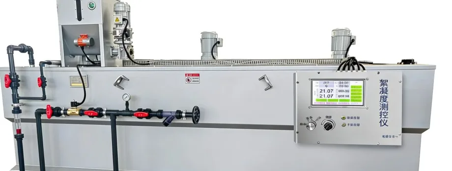
Who runs the plant, and what handover includes
An MBR needs an operator who can read the membrane behaviour, keep the pre-treatment working and follow the cleaning routine. The plant can run with a one-button start and stop, but the membrane still needs attention, and the level of attention is set by the wastewater and by the operating discipline.
Operator training and handover are project items. The handover package covers the operating manual, the control and alarm list, the cleaning and stop/restart procedure, the spare-parts list and the remote-support route. The format, the language and the spare-parts holding are confirmed with the order. The operating discipline and the handover routine are the same as for a packaged plant, and commissioning and operating a packaged plant covers that handover.
What leaves the plant besides treated water
An MBR produces surplus sludge, and over its life it produces spent membrane modules and cleaning waste. Each is a separate waste with its own handling and disposal route, and the route follows the local rule and the project waste classification rather than a generic statement.
- Surplus sludge — taken from the biological tank and dewatered; the volume and the disposal route are project items.
- Spent membrane modules — replaced at the end of their life and disposed of under the local rule for the module material.
- Cleaning waste — the spent cleaning solution is collected and handled under the local rule, not discharged to the process.
The equipment collects and contains these streams; the legal disposal route and the licensed contractor are confirmed for the site, because they change with the jurisdiction and with the waste classification.
Power, air and chemicals: what the utilities have to carry
Installed power is fixed per project. The nameplate voltage, phase and frequency are set from the site electrical data and confirmed on the nameplate with the order; the page does not publish a single connected load, because it moves with the blowers, the pumps and the membrane aeration the duty needs.
Aeration is the continuous utility. The model table gives the air demand that rises with capacity, and the blowers are sized against it; the membrane aeration and the biological aeration are both part of that demand. Cleaning chemicals and cleaning water are consumed on the cleaning schedule, and the chemical list comes from the membrane supplier.
The control philosophy — a local PLC with the degree of automation agreed for the site — is confirmed during detailed design from the operator profile and the remote-support arrangement, not fixed by the model number.
What drives the running cost, without inventing a price
The running cost of an MBR has four parts: aeration energy, because the blowers and the permeate pumps run while the plant is working; membrane replacement, because the module is a wearing part; cleaning chemicals and cleaning water; and operator attention. Membrane replacement is the cost that does not go away, and it is the reason a membrane plant is compared over its whole life rather than on the purchase price.
We do not publish a price for the plant or a unit cost for the membrane. The tariff, the load, the membrane datasheet and the local disposal route decide it, and a number invented here would be wrong for the next project. The four parts are what a project budget has to carry; the figures are confirmed with the offer and the membrane supplier.
The membrane datasheet and the records a project can use
The documents that answer the membrane question are issued with the order: the membrane datasheet, the design flux and membrane area, the O&M plan with the cleaning and replacement guidance, and the effluent test conditions. Factory and site tests, the operating manual, the control and alarm list and the spare-parts list are part of the handover.
Project references are used only with the customer authorisation and only with the documented result. A reference is offered as evidence of a duty, not as a promise that the next project will reach the same number.
Specification parameters
The rows below set out the fields a membrane plant purchase turns on. None of them is a single catalogue constant across the series; each is fixed for the project and stated in the offer or the project documents.
Wide table: scroll sideways to see every column.
| Parameter | How it is fixed |
|---|---|
| Standard supply platform | A packaged biological treatment and membrane separation unit, factory-assembled for site connection and commissioning. |
| Design flow | 0.5–10 m³/h (12–240 m³/day) per unit; larger flows use units in parallel or a custom build. |
| Membrane type and supplier | The module make and model are confirmed with the membrane supplier at the order stage; the module is supplied with the packaged unit as part of our scope unless the offer names a nominated vendor. |
| Design flux and membrane area | Project design outputs calculated from the design flow, peak flow, mixed liquor concentration and fouling load; issued with the project documents. |
| Effluent quality | Designed against the destination discharge or reuse standard. Grade 1A is reached directly in common engineering practice, not as a guarantee; the effluent guarantee, the sampling point and the test method are written into the project contract. |
| Power supply | The nameplate voltage, phase and frequency are set from the site electrical data and confirmed on the nameplate with the order. |
| Control mode | The control philosophy — a local PLC with the automation agreed during detailed design — is confirmed from the operator profile. |
| Installation | Installation is confirmed from the site layout and foundation drawing; the unit is set on a prepared foundation and connected to power, inlet, outlet and drain. |
| Footprint | 3.5 × 1.5 × 2 m to 15 × 2.5 × 2.5 m, depending on capacity. |
Membrane plant specification boundaries
Select a base model by flow
Start with the design flow and the peak factor to choose a base capacity. The standard CXMBR series covers 0.5–10 m³/h (12–240 m³/day) per unit. The 20 m³/h line is supplied as two units; larger flows use additional units in parallel or a custom build. The table is a selection reference, not a fixed-scope package offer. The final membrane configuration, model, unit count and scope of supply are confirmed against the influent, the discharge or reuse target, the site conditions and the power supply.
Wide table: scroll sideways to see every column.
| Model | Capacity (m³/h) | Dimensions L × W × H (mm) | Units | Weight (t) | Air demand (m³/min) |
|---|---|---|---|---|---|
| CXMBR-0.5 | 0.5 | 3000 × 1500 × 2000 | 1 | 1.5 | 0.15 |
| CXMBR-1 | 1 | 4000 × 1500 × 2000 | 1 | 1.7 | 0.3 |
| CXMBR-2 | 2 | 5000 × 2000 × 2000 | 1 | 2.5 | 0.6 |
| CXMBR-3 | 3 | 7000 × 2000 × 2500 | 1 | 3.5 | 0.9 |
| CXMBR-5 | 5 | 10000 × 2500 × 2500 | 1 | 4.5 | 1.5 |
| CXMBR-10 | 10 | 16000 × 2500 × 2500 | 1 | 8.4 | 3 |
| CXMBR-20 | 20 | 16000 × 2500 × 2500 | 2 | 16.8 | 6 |
CXMBR base models (catalogue outline data)
How to read the table
Dimensions are reference outline dimensions and weights are approximate equipment weights. Both are confirmed against the actual build once the site conditions are known. Air demand is the catalogue figure for the blower selection and is confirmed in the project design.
Related pages
Get a configuration and quotation for your project
Share what you know about the wastewater, flow and project location. We will review the information and confirm what else is needed for a quotation. You can leave details blank if they are not yet known.