
On this page
The work falls into four stages. The stages are a reading guide; the twelve numbered steps below remain the installation sequence.
- Preparation. Site, foundation, lifting and the delivery check.
- Main connections. Primary, secondary and mixing chambers, air duct and valves, fuel tank, purification chamber and chimney.
- Electrical and burners. Blower, temperature controllers, burners, fuel and power.
- Commissioning checks. Final bolt and valve checks, and the preheat run before the first load.
During preparation, use medical waste incinerator emission standards by country to identify conditions to verify against the project permit, and the incinerator capacity calculator for a preliminary capacity estimate. Confirm the final treatment duty and installation requirements for the project.
Before the delivery arrives: site, foundation and lifting
The site owes the machine three things before anything is unloaded: a reinforced, levelled foundation that carries the weight, clear working space around the unit with a safety passage and a material storage area, and a lifting plan. The foundation is levelled with a spirit level, correcting any tilt with inclined shim irons and steel plates before the first module is set down.
- Lifting is planned, not improvised: a trial lift comes first, and the formal lift starts only after everything checks out.
- Padding goes wherever a lifting rope touches the machine, so a sharp edge cannot cut the rope.
- Nobody works beneath the unit during hoisting; lifting eyes are checked before the lift; the load stays level all the way.
The delivery checklist
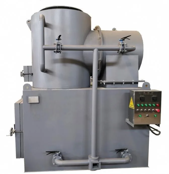
An incinerator delivery checklist is worked through on the day the truck is unloaded, not after the crane leaves. The furnace body consists of the primary combustion chamber, the secondary combustion chamber, the mixing chamber, the flue gas purification chamber, the fuel tank and the chimney; the accessories are two burners and one air-supply blower. Each module is counted and inspected against the list below.
Wide table: scroll sideways to see every column.
| Item | Qty | What to check |
|---|---|---|
| Primary combustion chamber | 1 | Control cabinet is mounted on it; heaviest module, set first |
| Secondary combustion chamber | 1 | Ships with sealing rope and fastening bolts |
| Mixing combustion chamber | 1 | Joins the secondary chamber before the pair is lifted on |
| Flue gas purification chamber | 1 | Observation port must end up facing the main furnace door |
| Fuel tank | 1 | Mounts on the mixing-chamber fixing plate |
| Chimney sections | 2 | Height can be customised to the site |
| Air duct with wafer butterfly valves | 1 + 4 | Valves ship loose and are fitted during assembly |
| Burners | 2 | One per chamber; the secondary-chamber burner has the higher heat value |
| Air-supply blower | 1 | Quick-connect plug to the control cabinet |
| Spares and documents | 1 set | Two fuel nozzles, two fuse boxes, one photocell, certificate and manual |
The incinerator delivery checklist for the CXMWI-200 configuration; other sizes in the series ship the same modules.
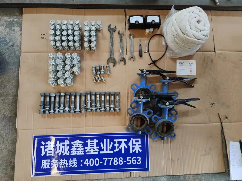
The fastener pack is part of the checklist, because assembly stalls without it: 18 sets of M18×60, 52 sets of M16×60, 16 sets of M16×100, 4 sets of M10×45 (with four more inside each burner box) and 4 sets of M8×25, plus the sealing rope, the installation wrench and a screwdriver. The sealing rope is asbestos as standard; a ceramic-fibre rope can be fitted on request for markets that restrict asbestos. Counts vary slightly between furnace models.
The twelve installation steps
How to install a waste incinerator of this design is a fixed sequence: each module bolts onto the one below it, and each step is a check on the step before. The sequence below is the one our installation crews follow on site.
- 1. Set the primary chamber. Hoist the primary combustion chamber onto its designated position on the levelled foundation.
- 2. Join the secondary and mixing chambers. Lift the secondary chamber by its top lifting holes, connect it to the mixing chamber, pre-tighten the two diagonal bolts to align the pair, then fit and tighten the remaining bolts.
- 3. Lift the pair onto the primary chamber. Lay the sealing rope flat on the flange — wet it first — hoist the assembly on, fine-adjust with a pry bar, hand-tighten the four corner bolts, then fit all bolts.
- 4. Fit the air duct and the four butterfly valves. Keep the duct vertical during the lift. Seat each wafer valve between its flanges with the bolts only inserted, check every disc can open fully, and tighten only when all four valves are in place.
- 5. Mount the fuel tank. Fix it to the mixing-chamber plate once all four bolt sets are in their holes, then connect the tank to the oil pot with the transparent steel-wire hose and tighten the hose clamps.
- 6. Add the purification chamber. Sealing rope on the flange, hoist with the observation port facing the main furnace door, fine-adjust, then fit and tighten all bolts.
- 7. Stack the chimney. Sealing rope on the flange; the chimney height follows the site conditions.
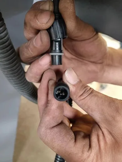
- 8. Connect the blower. Bolt it to the air-duct flange through the rubber gasket — tight, so vibration cannot damage it — then mate its quick-connect plug with the control cabinet, aligning the grooves, and screw the protective sleeve tight.
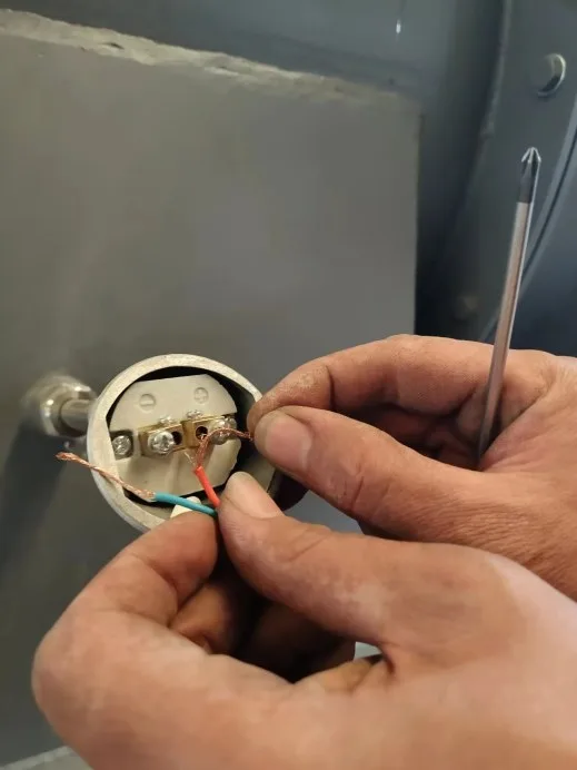
- 9. Wire the temperature controllers. The primary and secondary chamber controllers are different instruments; wire red to the positive terminal and green (or blue) to the negative, then close the protective covers.
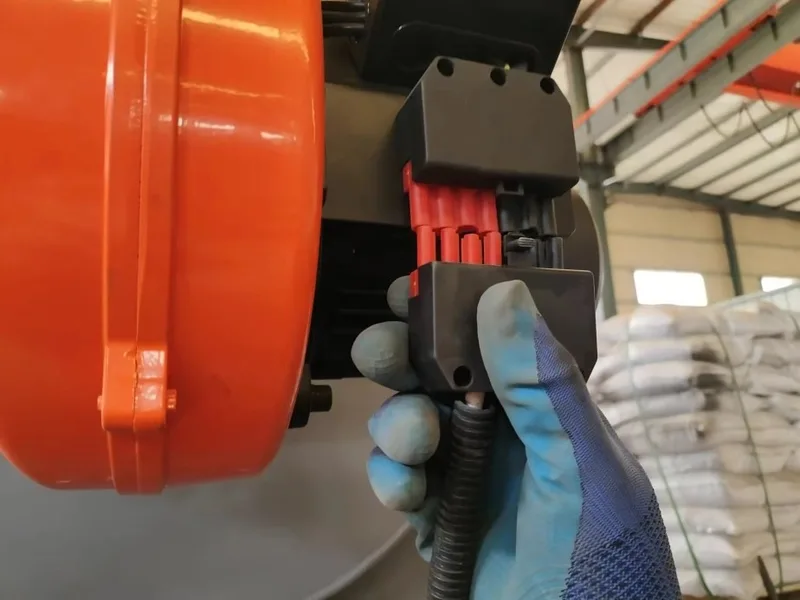
- 10. Fit the burners. Each burner bolts into its firing port with its insulating gasket, the quick-connect plugs mate by colour, and the oil line with the filter goes to the “▲” port while the unfiltered return line goes to the “▼” port.
- 11. Fuel and power. Fill the tank with the diesel grade that matches the lowest ambient temperature on site — 0# diesel in normal conditions. The standard supply is single-phase; three-phase at the required voltage and frequency is supplied on request. Confirm every connection is firm, with no looseness, oxidation or poor contact, before closing the main switch.
- 12. Final checks. Every bolt tight, every valve fully open. Installation is complete and commissioning can begin.
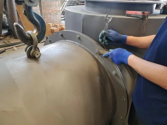
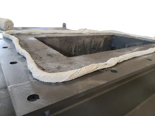
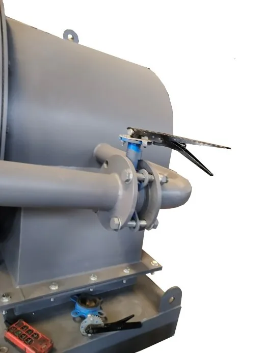
Two rules run through the whole sequence. Every flange joint gets its sealing rope, wetted and laid flat. And every flange is tightened diagonally and crosswise with the supplied wrench — a bolt that is skipped, or tightened twice while its neighbour is loose, leaves the joint uneven and the flue gas path leaking.
First firing: preheat before the first load
Preheating a new incinerator is not optional. The refractory and the furnace structure hold moisture from manufacture, transport and storage, and the first firing is a low-temperature preheating run that lets that moisture evaporate before any waste is loaded. A furnace taken straight to working temperature while still damp deforms — the body and the door move, and the sealing faces no longer meet. The first run is for the furnace, not for the waste.
Routine maintenance: the three wear parts
Incinerator burner maintenance on this design comes down to three parts the site can change itself, all shipped as spares in the delivery: the photoelectric cell, the fuse box and the fuel nozzle.
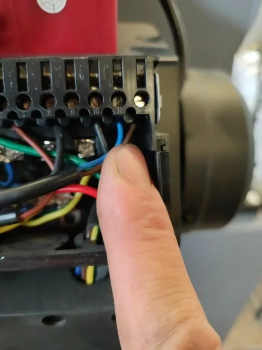
- Photoelectric cell. Cut the power first. Pull the cell out from the side of the burner, move the wires from terminals 11 and 12 onto the new cell in the same positions, insert it and switch the power back on.
- Fuse box. The fuse box snap-fits at the end of the burner; press the marked point with a flat screwdriver, pry both sides up and lift it out. The replacement must be pressed firmly home — a fuse box that is not fully seated is the classic reason a burner will not ignite after servicing.
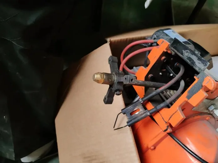
- Fuel nozzle. Remove the burner, detach the head from the body, take out the swirler and the ignition electrode to expose the nozzle, unscrew it and fit the spare. Refit the electrode, the swirler and the head in order, and mount the burner back on the furnace.
The full manual, and what to send when something does not fit
This article condenses the guide that ships with every unit. The complete document — with the full delivery list, the step photographs and the maintenance procedures in one file — is the small waste incinerator installation guide (PDF), the same document our technicians hand to the crew on site.
When a connection on site does not match the guide, a photograph of the joint sent to our service team gets a faster answer than a description. And where the question is upstream of installation — which model, which capacity, which flue-gas configuration — that is confirmed with us against the waste type, the daily volume and the emission standard that applies, as set out on the small-scale incinerator page and the medical waste range.