
On this page
What is the activated sludge process?
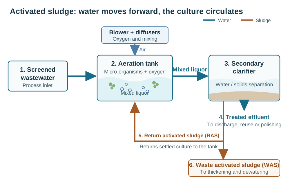
The activated sludge process is a biological wastewater treatment process in which suspended micro-organisms remove biodegradable pollution while air and mixing keep them in contact with the wastewater. The resulting biological solids are separated in a secondary clarifier. Most return to the aeration tank as return activated sludge, while a controlled amount leaves as waste activated sludge.
The culture oxidises the biodegradable organic matter described by BOD and COD and, where the solids are retained long enough, converts ammonia to nitrate. Turning nitrate into nitrogen gas requires a separate zone without dissolved oxygen; the A²/O process guide explains that arrangement. The process reduces organic matter and nutrients; it does not by itself guarantee a particular effluent limit.
Activated sludge process flow: six steps
Wide table: scroll sideways to see every column.
| Step | Where it happens | What happens |
|---|---|---|
| 1. Mix | Aeration tank inlet | Screened wastewater mixes with returned biological solids. The mixture is called mixed liquor. |
| 2. Aerate | Aeration tank | A blower and diffusers, or mechanical aerators, supply oxygen and keep the biological flocs suspended. |
| 3. Treat | Aeration tank and any configured reaction zones | Micro-organisms use biodegradable organic matter. With a suitable sludge age and oxygen supply, nitrifying organisms also convert ammonia to nitrate. |
| 4. Separate | Secondary clarifier | The biological flocs settle, leaving a clarified water layer above a concentrated sludge layer. |
| 5. Discharge or polish | Clarifier overflow | Treated effluent goes to the permitted outlet, reuse system, disinfection or further nutrient removal required by the project. |
| 6. Return and waste | Clarifier underflow | Most settled sludge returns to the aeration tank as RAS. A smaller WAS stream goes to thickening and dewatering so the solids inventory does not grow without limit. |
The six steps of a conventional activated sludge process. Pretreatment and downstream nutrient removal or disinfection are added to suit the site.
The three parts that keep the culture working
Wide table: scroll sideways to see every column.
| Part | Its job | What the design must check |
|---|---|---|
| Aeration tank and aeration system | Hold the mixed liquor, supply oxygen and maintain mixing | Biological solids inventory, oxygen demand, tank volume, diffuser or aerator duty and mixing at operating level |
| Secondary clarifier | Separate treated water from the biological solids | Surface and solids loading, settling behaviour, blanket depth and effluent solids |
| Return and waste sludge system | Return the culture and remove excess solids | RAS concentration and flow, WAS flow, pump range and the solids mass balance that sets sludge age |
Once that flow path is clear, the design question is not simply “how large is the tank?” Sludge age, F/M, return sludge flow and tank volume are four connected views of the same solids and hydraulic balances. Fixing one in isolation can produce a tank that is too small, under-aerated or unable to retain its solids.
Decision one: sludge age in wastewater treatment
The sludge age is the average time a particle of solids spends in the system: the mass of solids held in the aeration tank and the clarifier divided by the mass taken out each day, in days. It is also called the solids retention time, or SRT.
It is the dial that decides most of the rest. A short age keeps the culture young and fast-growing: more excess sludge, and no time to establish the slower-growing organisms. Nitrifiers grow more slowly than the organisms that remove organic matter, so a plant that has to nitrify must hold its sludge long enough that they are retained rather than washed out; the age needed rises as the water gets colder.
Commonly quoted figures put conventional activated sludge at roughly 5 to 15 days and extended aeration at roughly 20 to 30 days. Those ranges describe common practice rather than your water, and should be read as a starting method rather than as a specification. The age a plant needs follows from the effluent requirement — whether ammonia has to be oxidised, and at what winter temperature — and from how well the sludge settles.
How to determine it: work back from the discharge standard to the slowest organism the plant has to retain at the coldest water it will see, then confirm it on the running plant, where the mixed liquor solids and the sludge wasted each day give the age actually being run. The sludge age band for extended aeration, what holds it and what it costs are set out on the extended aeration page.
Decision two: the food to microorganism ratio in wastewater treatment
The food to microorganism ratio, written F/M almost everywhere, is the mass of food arriving each day divided by the mass of organisms kept to consume it: BOD, occasionally COD, over mixed liquor suspended solids, in kilograms of BOD per kilogram of MLSS per day.
F/M and sludge age are the same dial seen from two sides: hold more sludge against the same load and the ratio falls, waste more sludge and it rises. A high ratio favours rapid growth, a bulky floc and more excess sludge; a low ratio means food is scarce, growth is slower, the culture is steadier and nitrification is easier to hold, until the floc becomes pin-point and slow to settle.
Starting figures often quoted for a conventional plant sit around 0.2 to 0.4 kg BOD per kg MLSS per day, with extended aeration lower, of the order of 0.05 to 0.15. Read them as a starting method rather than as a specification: the load in the ratio is your influent, not a typical one.
How to determine it: the ratio is rarely a set point in its own right. It is calculated from the design load and the solids concentration the tank will hold, and checked from the operating record — influent flow and BOD with the mixed liquor suspended solids. Where the influent analysis is uncertain, the design influent quality chart sets out which figures are worth trusting.
Decision three: the return activated sludge rate
The return rate is the flow of settled sludge pumped from the bottom of the clarifier back to the aeration tank, usually stated as a ratio to the incoming flow. Without it, the organisms that do the work leave with the waste sludge and the population in the aeration tank falls until the process fails.
The rate sets two things at once: the mixed liquor suspended solids the aeration tank runs at, because the sludge returned into a given volume sets that figure, and the hydraulic load on the clarifier, because every litre returned passes through it twice. Return too little and the solids blanket rises until solids leave with the effluent; too much and the clarifier is overloaded, which carries the blanket out just as effectively.
The rate follows from the solids concentration the tank needs and the concentration of the sludge being returned, and the second is a property of the sludge rather than of the pump. Settleability is measured as the sludge volume index, and a sludge that settles well can be returned at a lower ratio. Ratios of the order of 0.5 to 1 times the influent flow are commonly quoted for a conventional plant, and the ratio has to follow the sludge the plant actually grows.
One line worth drawing here: the return sludge line is not the internal recycle that carries nitrified liquor to an anoxic zone. Both are called recycle, and they do opposite things — one returns the culture, the other returns nitrate.
Decision four: the aeration tank in a wastewater treatment plant
The aeration tank is where the first three decisions become concrete. Its volume is the mass of solids the plant has to hold, which the sludge age and the load decide, divided by the mixed liquor suspended solids concentration the tank will run at. Two consequences follow that otherwise look like rules of thumb: a higher mixed liquor concentration lets the same load be treated in a smaller tank, and a longer sludge age at a fixed concentration needs a larger one.
Volume is only half the decision. The tank also has to deliver oxygen, and the demand has two parts: the carbonaceous part, which follows the organic load actually oxidised, and the nitrogenous part, which appears when the plant nitrifies. Oxidising ammonia to nitrate consumes a fixed quantity of oxygen per kilogram of nitrogen, of the order of 4.57 kg. A plant asked to nitrify therefore needs more air than carbon removal alone would.
Commonly quoted mixed liquor figures are of the order of 2,000 to 4,000 mg/L for conventional activated sludge and 3,000 to 6,000 mg/L for extended aeration. Read them as a starting method rather than as a specification: the concentration your clarifier can hold without losing solids is the real limit, and it is determined on the plant rather than from a table.
How to determine it: the oxygen demand comes from the load removed and the nitrogen oxidised, then from the transfer efficiency of the diffusers at the depth of that basin, which is equipment-specific.
Why the four move together
A change to any one of the four arrives at the other three:
- Raise the sludge age and the tank has to hold more solids, at a higher mixed liquor concentration or in a larger volume.
- Raise the mixed liquor concentration and the return rate rises with it, which loads the clarifier harder.
- Lower the food to microorganism ratio and the culture can retain slower-growing organisms more readily; where nitrification is required, its oxygen demand must then be included in the aeration design.
- Push any of the three beyond what the sludge can settle at, and solids leave over the weir whatever the drawing says.
The order of the work follows: the effluent requirement fixes the sludge age, the sludge age and the load fix the mass of solids, the clarifier fixes the concentration it can hold, and the mass with the concentration fixes the volume.
Worked example: from wastewater load to tank and return flow
The following is an arithmetic demonstration, not a project case study or a recommended plant design. Every input is assumed so that the formulas can be checked end to end. The example uses an aeration-tank-only solids inventory and a net observed yield expressed on the same MLSS basis as the tank inventory.
Wide table: scroll sideways to see every column.
| Assumed input | Value | Meaning |
|---|---|---|
| Average flow, Q | 1,000 m³/d | Flow used for this first-pass example |
| Influent and effluent BOD₅ | 250 and 20 mg/L | Used to calculate incoming and removed organic loads |
| Target SRT | 10 days | Assumed biological solids retention time |
| Aeration-tank MLSS, X | 3,000 mg/L = 3 kg/m³ | Assumed solids concentration |
| Return-sludge solids, Xr | 8,000 mg/L = 8 kg/m³ | Assumed concentration in both the RAS and WAS streams |
| Effluent suspended solids, Xe | 10 mg/L = 0.01 kg/m³ | Included in the solids-leaving term |
| Net observed yield | 0.5 kg MLSS/kg BOD removed | An illustrative assumption after decay, not a universal yield coefficient |
Demonstration inputs only. They are not measurements from our equipment or design values for another plant.
Wide table: scroll sideways to see every column.
| Calculation | Substitution | Result |
|---|---|---|
| Incoming BOD load | 1,000 × 250 ÷ 1,000 | 250 kg BOD/d |
| Removed BOD load | 1,000 × (250 − 20) ÷ 1,000 | 230 kg BOD/d |
| Net solids production, Px | 0.5 × 230 | 115 kg MLSS/d |
| Required solids inventory | 10 × 115 | 1,150 kg MLSS |
| Aeration-tank volume, V | 1,150 ÷ 3 | 383 m³ |
| Hydraulic retention time | 383 ÷ 1,000 × 24 | 9.2 hours |
| Food to microorganism ratio | 250 ÷ 1,150 | 0.22 kg BOD/kg MLSS·d |
| Return ratio, r | 3 ÷ (8 − 3) | 0.60 |
| Return flow, Qr | 0.60 × 1,000 | 600 m³/d |
| Effluent solids leaving | 1,000 × 10 ÷ 1,000 | 10 kg/d |
| Waste flow from the RAS line, Qw | (115 − 10) ÷ 8 | 13.1 m³/d |
One internally consistent activated sludge calculation. Rounded displayed values may differ slightly if used as inputs to a later step.
The last row closes the balance: 13.1 m³/d of waste sludge at 8 kg/m³ removes about 105 kg/d, and the effluent carries another 10 kg/d. Together they equal the assumed 115 kg/d solids production, so the 10-day inventory remains steady. The 0.60 return ratio is a first-pass result from the simplified relation above, not an instruction to set every plant to 60%.
A real design must still establish the wastewater-specific yield and decay terms, winter nitrification requirement, peak hydraulic and solids loads, clarifier loading, sludge settleability and oxygen-transfer conditions. Those checks can change the volume, return system and blower duty even when this arithmetic is correct.
Common mistakes
- Sizing the tank from residence time alone, when two tanks with the same retention time hold very different quantities of biomass.
- Setting a sludge age that suits the nitrifiers at summer temperature, when the minimum nitrification age rises as the water cools.
- Treating the sludge return as a pump selection.
- Reading the ratio from the design load alone, when the operating record is the measurement.
- Assuming the plant will run at the design mixed liquor concentration when the clarifier cannot hold it.
- Leaving the clarifier out of the calculation: its surface area sets the ceiling on the concentration the train can carry.
- Copying a sludge age from a plant on different water, when age, concentration and settleability travel together.
Self-check before the numbers are fixed
- Is the effluent requirement written as what has to be removed — organics, ammonia, nitrogen, phosphorus — rather than as a process name?
- Is the design temperature the coldest the plant will operate at?
- Is the sludge age in wastewater treatment set from the slowest organism the plant must retain at that temperature?
- Is the mixed liquor concentration one the clarifier can hold, checked against the sludge volume index expected?
- Has the return activated sludge rate been derived from the target concentration and the return sludge concentration?
- Is the food to microorganism ratio in wastewater treatment calculated from the design load and the mixed liquor the tank will actually hold?
- Has the oxygen demand been built from the carbon load and the nitrogen load separately?
- Has the excess sludge production been estimated, so the wasting and dewatering duty is known?
- Is the aeration tank in a wastewater treatment plant sized from the mass of solids and the concentration together, rather than from a residence time?
Sources and verification
- Sludge age: 10–20 days measured at municipal activated sludge plants, PLOS ONE (2025), DOI 10.1371/journal.pone.0331211. This is a measured plant range, not a design recommendation; the 5–15 day and 20–30 day bands above describe design practice.
- F/M ratio: 0.2–0.6 kg BOD per kg MLVSS per day for complete-mix reactors, MDPI IJERPH (2022), DOI 10.3390/ijerph19105985. The published figure is on an MLVSS basis; the 0.2–0.4 band above is on an MLSS basis, and the two are not interchangeable.
- Dissolved oxygen and return flows: constant-DO control at 1–3 mg/L and return flows of 50–100% of influent, MDPI Processes (2019), DOI 10.3390/pr7050311.
- Return ratios: RAS between 0.25 and 1.5 times influent flow and internal recycle at 200% of influent in a full-scale case, Environmental Monitoring and Assessment (2022), DOI 10.1007/s10661-022-09968-9.
- Worked example: the equations above are solids and hydraulic balances. All example inputs are explicit assumptions chosen to demonstrate the arithmetic; they are not plant measurements, equipment performance data or recommended design values.
From the process diagram to a design basis
The diagram explains the circulating culture; the four decisions and worked example turn that process into a solids inventory, tank volume and return flow. The tank volume and HRT calculator checks the hydraulic side, while the plant selection and sizing guide starts from design flow, influent analysis and discharge standard. Where the duty suits a packaged membrane process, the integrated MBR equipment page covers that configuration. We confirm the process and equipment basis for your wastewater rather than adopting the demonstration values above as a specification.