
Integrated water purifier.
Coagulation, settling and filtration in one fabricated body, sized from the raw water — with the outlet boundary, filter medium, backwash and residual streams written down.
What an integrated water purifier is, and what the site still does
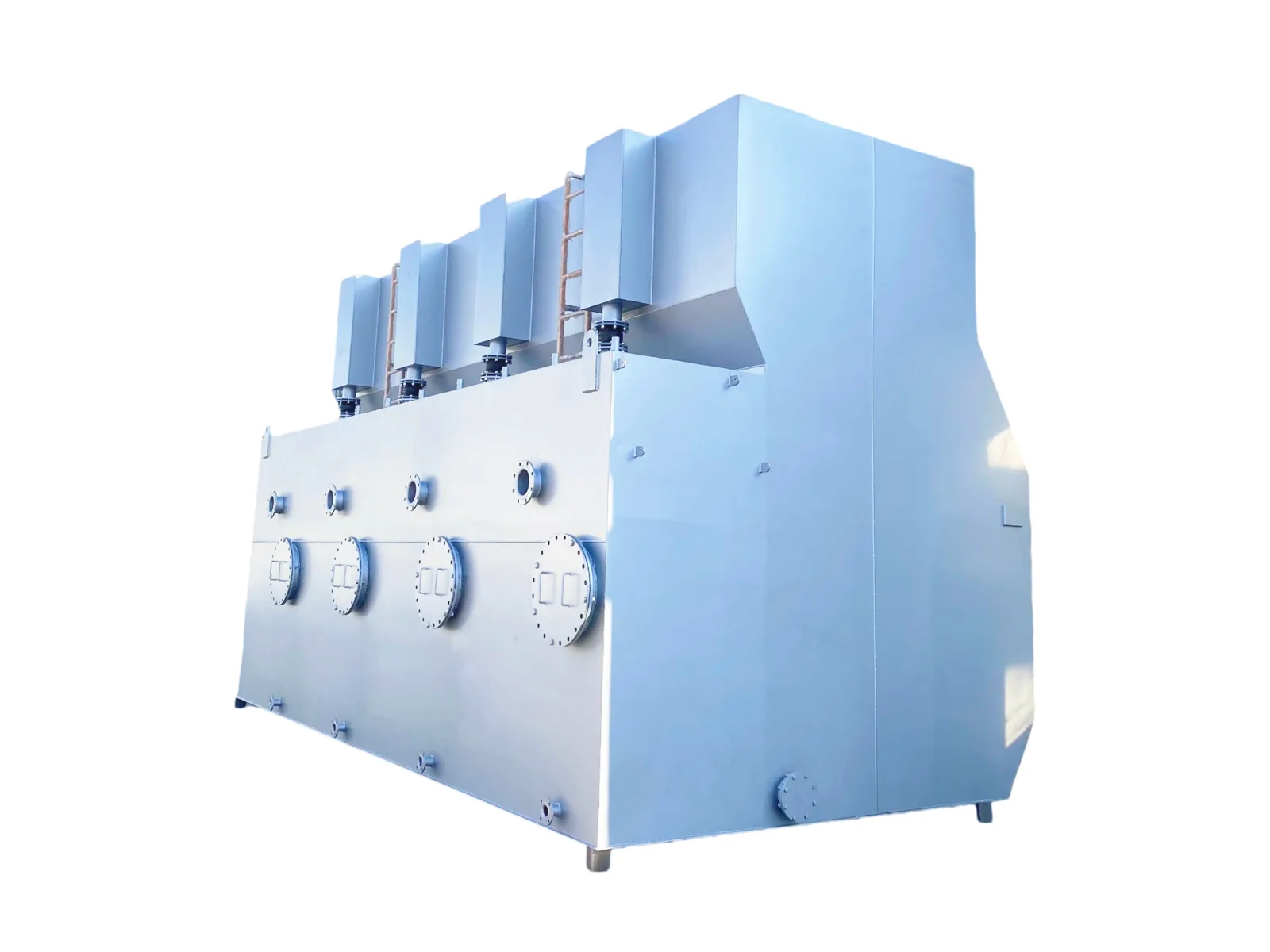
An integrated water purifier is a packaged treatment unit for surface water or a light industrial water source. Dosing and coagulation, settling and filtration are built into one fabricated body rather than three separate tanks: coagulant is dosed into the incoming water, the floc forms and settles in the clarification chamber, and the settled water passes to the filter bed before it leaves the unit. Sharing one body and one frame suits a site with no treatment building, and the raw water decides the arrangement, so sizing starts from a water analysis rather than from a flow figure alone. The unit is assembled and tested at our factory before shipment; on site the foundation and civil works, the inlet and outlet pipework, the chemical storage and dosing supply where it is not part of the packaged scope, the power supply and earthing, the waste line, the disinfection stage where the project needs one, the lifting and placement and the permits are site work.
The raw water sets the envelope: turbidity, colour, algae and the season
An integrated water purifier is sized from the raw water, not from a flow figure alone. The unit is a coagulation, settling and filtration train for surface water: a river, a canal, a reservoir or a light industrial source. Our published CXJS integrated water purifier is offered for surface water with a turbidity up to 3000 mg/L, which is the catalogue envelope rather than a promise for every source. The same envelope is where the dissolved load is checked: salinity, fluoride, arsenic, iron and manganese are not removed by this train, and a source that carries them needs a separate stage.
Four raw-water values decide how much work each stage does: turbidity and its seasonal peak, colour, algae, and the suspended solids that arrive with a rain event. A source that is clear at the end of the dry season and turbid after the first rain is sized at the difficult end of the year, not on an annual mean. The raw-water analysis and the design flow are the two inputs we ask for before a size is fixed, and the source-water article sets out how the analysis turns into a train.
- Turbidity: the catalogue envelope is 3000 mg/L. A source above it, or one whose peaks are not characterised, is outside the published envelope and needs a different train.
- Colour and algae: both load the coagulation and clarification stages. The dose and the settling area are set from the analysis, not from a single turbidity figure.
- Dissolved load: salinity, fluoride, arsenic, iron and manganese stay in the water through this unit. They are a separate stage, and the influent quality chart gives the reference ranges behind that decision.
Not a drinking-water compliance statement
Clarification and filtration are one stage of a water supply. This unit does not disinfect, and we do not claim drinking-water compliance from it; a supply intended for drinking needs disinfection, source protection and compliance testing against the destination standard, and those sit outside our supply.
The outlet boundary, and how it is tested
The outlet is a project requirement, not a catalogue guarantee. The unit removes turbidity, colour and suspended solids by coagulation, settling and filtration; the published CXYJ river-water purifier catalogue lists an outlet turbidity of 5 mg/L at an inlet turbidity of 3000 mg/L. That value is a catalogue reference at the stated inlet condition, not a guarantee for a different source, and it is not a drinking-water compliance statement.
The outlet is tested on the project water. Turbidity is read by nephelometry and reported in NTU; colour is read against a colour standard; suspended solids are measured by filtration and gravimetry. The sample point, the test method and the acceptance value are written into the project contract, and the test is run on the commissioned unit rather than on a catalogue figure.
- Turbidity: nephelometry, reported in NTU. The catalogue prints the unit as mg/L; the project test reports NTU.
- Colour: measured against a colour standard in Hazen units, on a filtered sample.
- Suspended solids: measured by filtration and gravimetry, on the same sample as the turbidity.
What the outlet boundary is not
It is not a drinking-water compliance statement, not a disinfection guarantee, and not a promise that a different raw water will reach the same figure. The catalogue value belongs to the stated inlet condition; the project value belongs to the project test.
The filter medium, the bed and the filtration rate
The filter bed is the barrier behind the clarification stage. The published catalogue gives a design filtration rate of 10 m/h and a settling surface load of 4.3 m³/h·m² for the CXYJ river-water purifier. Those two values set the plan area of the clarifier and the filter for a given flow; they are catalogue values, and the project design is confirmed against the actual water.
The medium grading, the bed depth and the choice between a single-medium and a multi-media bed are fixed per project. There is no universal grading that suits every source: a bed that is right for a low-turbidity river is not the bed for a source carrying algae or a high colour load. We confirm the grading and the depth against the raw-water analysis and the outlet requirement, and the drawing for the project carries the final values.
The filter is reached through the flanged covers on the body. The medium can be inspected and replaced without dismantling the unit, and the replacement interval is set by the operating record rather than by a fixed catalogue life.
Media are project-confirmed
Medium grading, bed depth and the single- or multi-media arrangement are confirmed per project against the water analysis; this page does not publish one grading for every source.
Backwash: intensity, duration and where the water goes
The unit backwashes the filter bed in place, with water. The published catalogue gives a backwash intensity of 15–18 L/s·m², adjustable, and a backwash duration of 1–5 min, adjustable. The body carries the backwash sequence, so the unit does not need a separate backwash pump or air compressor; the sequence is set on the control panel and confirmed at commissioning.
The backwash water carries the solids that were held in the bed. It leaves the unit on the waste line and goes to the plant sludge or equalisation system; it is not returned to the filtered-water outlet. The average self-consumption is about 3% of the treated volume on the published catalogue, and the actual figure is read from the operating record.
The volume per event follows from the filter area and the backwash intensity. For a worked example, a design flow of 50 m³/h at a filtration rate of 10 m/h gives a filter area of 5 m². At 15–18 L/s·m² the backwash flow is 75–90 L/s, or 270–324 m³/h, and a 1–5 min event uses 4.5–27 m³. At 3% self-consumption the average backwash water is 1.5 m³/h, or 36 m³/day on a 24-hour basis. These are engineering estimates from the stated inputs, not a measured volume.
Wide table: scroll sideways to see every column.
| Item | Value | Basis |
|---|---|---|
| Design flow | 50 m³/h | Worked-example input |
| Filtration rate | 10 m/h | Catalogue value |
| Filter area | 5 m² | 50 ÷ 10 |
| Backwash flow | 270–324 m³/h | 15–18 L/s·m² × 5 m² |
| Backwash volume per event | 4.5–27 m³ | 270–324 m³/h × 1–5 min |
| Average backwash water | 1.5 m³/h (36 m³/day) | 3% × 50 m³/h |
Backwash worked example. Engineering estimate from the catalogue intensity and the stated flow; the project volume is confirmed on the commissioned unit.
Estimate, not a measured volume
The volumes in this table are an engineering estimate from the stated inputs. The project backwash volume is measured at commissioning and recorded in the operating log.
Sludge, backwash water and the legal outlet
The unit produces two residual streams: the sludge that settles in the clarification zone and the backwash water that carries the solids out of the filter. There is no membrane concentrate stream in this unit, because the train has no membrane; if a membrane is added downstream, its concentrate is a separate stream and is not covered by this page.
The sludge quantity follows from the raw-water suspended solids that are removed and the coagulant that is dosed. For a worked example, 50 m³/h with 100 mg/L of suspended solids at the inlet and 10 mg/L at the outlet, plus a coagulant dose of 20 mg/L, gives 50 × (100 − 10) + 50 × 20 = 5500 g/h, or 5.5 kg of dry solids per hour. At 2% solids the wet sludge is about 275 L/h. The dose is a worked-example input, not a recommended dose; the actual dose comes from the jar test on the project water.
The legal outlet for the sludge and the backwash water is set by the destination regulator and by the permit for the site, not by us. The project operator is the generator of the residual and carries the disposal responsibility; the permit, the classification of the sludge and the receiving facility are confirmed before the unit is commissioned. We do not publish a single disposal route for every country, and a claim that the residuals are treated to standard is not a substitute for the permit.
Wide table: scroll sideways to see every column.
| Residual | Worked-example quantity | Basis |
|---|---|---|
| Sludge dry solids | 5.5 kg DS/h | 50 × (100 − 10) + 50 × 20 g/h |
| Wet sludge at 2% solids | 275 L/h | 5.5 kg/h ÷ 0.02 |
| Backwash water per event | 4.5–27 m³ | Backwash table above |
| Average backwash water | 1.5 m³/h | 3% × 50 m³/h |
Residual quantities for the worked example. Engineering estimate from the stated inputs; the project quantities are measured at commissioning.
The outlet is a permit question
The legal outlet and the sludge classification are set by the local authority and the project permit. The operator carries the generator responsibility; we supply the treatment unit, not the disposal route.
Integrated or split, and what fixes the size
The published CXYJ river-water purifier catalogue spans 10–200 m³/h across its models, with an operating pressure below 0.1 MPa and an inlet pressure of at least 0.09 MPa. The catalogue also gives a total retention time of 60–65 min and a unit height of about 2.9 m. That range is a catalogue reference for the river-water series, not a statement that every model is in stock or that the current CXJS build uses the same shell. The model, the chamber dimensions and the dosing arrangement are confirmed for the project.
An integrated unit suits a site with no treatment building, a small footprint and a single packaged train. A split arrangement is the better answer when the flow is beyond the published range, when the site wants separate chemical storage or a separate clarifier, when the raw water needs a stage this train does not have, or when the maintenance access or the foundation makes a single body impractical. The plant selection and sizing guide takes the flow and the analysis through that decision.
The dose is set by a jar test on the project water, not by a catalogue figure. The jar test gives the coagulant and polymer dose; the oxidation or adsorption stage, where the water needs one, is a separate test and a separate unit. The chemical and advanced treatment page covers those stages.
Model and dimensions are project-confirmed
Capacity, chamber dimensions and the dosing arrangement are confirmed against the design flow and the water analysis; the published range is a catalogue reference, not a guarantee that a particular model fits a particular source.
Where our supply ends and your site work begins
In our supply sit the fabricated body, the treatment chambers, the filter bed and the in-body backwash sequence, the mixing drives and the control panel that runs the sequence. The exact split is fixed in the commercial offer for the project.
On site sit the foundation and the civil works, the inlet and outlet pipework to the unit, the chemical storage and dosing supply where it is not part of the packaged scope, the power supply and earthing, the waste line to the sludge or equalisation system, the disinfection stage where the project needs one, and the permits. The unit is assembled and tested at our factory before shipment; the site work and the commissioning plan are agreed before delivery.
The boundary matters because a packaged unit is not a turnkey plant. The outlet test, the sludge disposal and the drinking-water compliance of a supply are project responsibilities; we supply the clarification and filtration stage and the documentation that goes with it.
Acceptance is written into the contract: factory acceptance tests before shipment, site acceptance tests after installation, and a performance test on the outlet turbidity, colour and suspended solids at the stated inlet condition, with the sampling point, the sample handling, the test methods — nephelometry in NTU for turbidity, a colour standard in Hazen units for colour, filtration and gravimetry for suspended solids — the inlet condition at the time of the test and the acceptance value agreed for the project, the party that carries a missed result named, and a failed result rectified and retested as agreed. Acceptance records are project documents; when you compare quotations, ask for the acceptance section of the contract.
The offer fixes the split
The supply split is written into the commercial offer. This page describes the usual boundary; it is not a substitute for the scope list in the offer.
Operation, training and the documents behind the figures
The unit is operated from the control panel; the backwash sequence, the dose and the outlet check are the routine tasks. We hand over an operation and maintenance manual and operator training with the unit, and the manual is written for the project rather than as a generic catalogue.
The documents behind the published figures are the catalogue table for the CXYJ river-water purifier and the current CXJS product page. A project drawing, the medium specification and a treated-water test report are issued for the project; we do not publish a third-party outlet test report or a drinking-water compliance certificate for this unit because neither is on file.
Spares follow the wear parts: the medium, the mixing drives and the control instruments. The recommended spares list and the response route are confirmed with the order.
What is not on file
A third-party treated-water test report, a drinking-water compliance certificate and a published case study are not on file. We do not publish them as if they were.