
On this page
What the patent covers
CN206600820U is a Chinese utility model, originally titled A waste incinerator. It was filed on 27 February 2017 and granted on 31 October 2017. The inventor is Rufeng Xu; the applicant is Shandong Innovation Huayi Environmental Engineering Co., Ltd. It carries seven claims — one independent, six dependent — and two figures.
Read as a two chamber incinerator design document rather than a product sheet, it is unusually complete: furnace, air supply, gas path and cooling loop all appear on one page. It was one of eight applications filed the same day; the other seven are water-treatment devices — a dissolved-air flotation oil remover, a scum scraper, an air-dissolving unit, a buried anaerobic tank, an integrated water purifier, a plate-and-frame filter press and a serpentine squeezing belt filter. This is the only non-water-treatment device in the batch: an early small-scale design from a company whose main line was water treatment, not a mature platform.
The patent is also no longer in force. The record shows it expired on 6 March 2026 for non-payment of the annual fee, short of the natural term that would have run to 27 February 2027. The document is public and the design is in the public domain. It publishes no temperature, no residence time, no destruction efficiency, no capacity and no emission figure; every performance figure used later in this article comes from product data and standards used elsewhere on the site.
The furnace: two chambers and one air supply
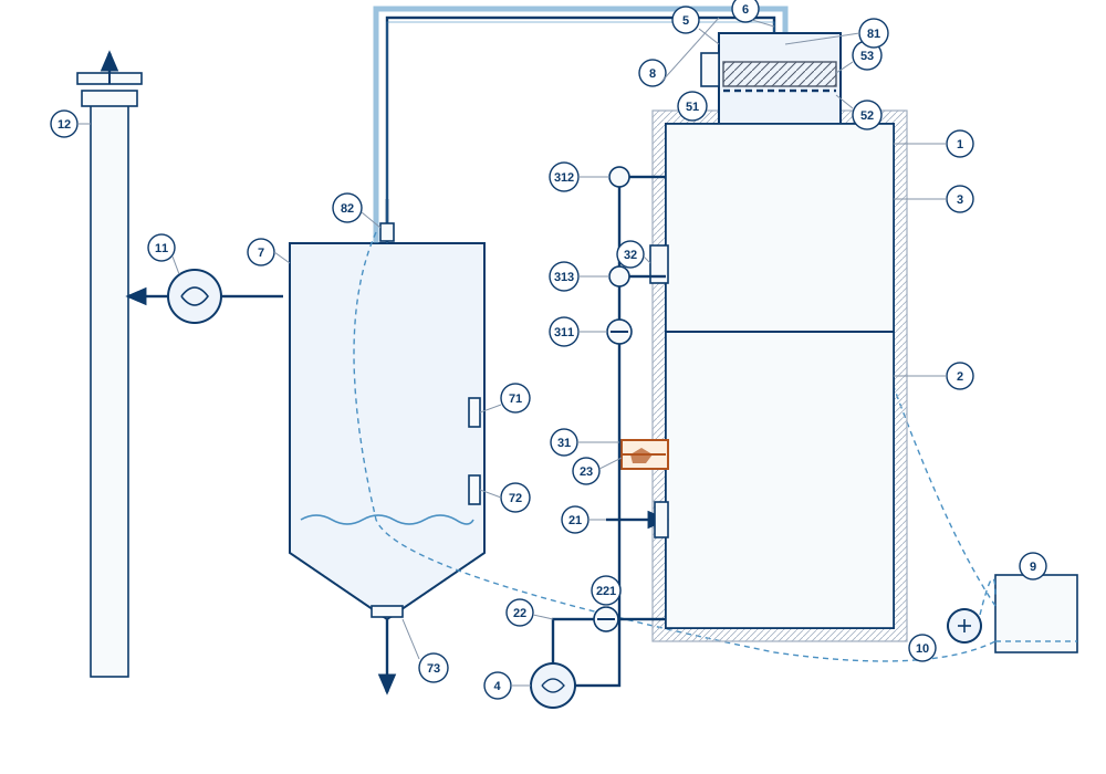
The furnace body 1 is a vertical stack of two chambers. The primary chamber 2 sits at the bottom and carries the waste inlet 21, the first air duct 22 and the burner 23. The secondary chamber 3 sits directly above and has one air duct, 31.
Air comes from a single blower 4, and it feeds both chambers. Duct 22 rises into the primary through a manual damper 221. Duct 31 runs to the secondary through damper 311, then splits into an upper branch 312 and a lower branch 313 entering at the top and bottom respectively. Two chambers, one blower, two hand valves.
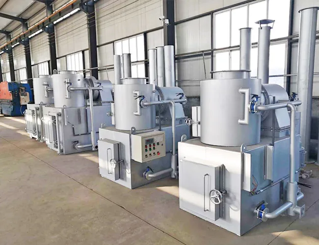
Which brings the question the drawing answers: how does a two chamber incinerator work? A single chamber burns the waste, but the gas above the burning surface still carries carbon monoxide and unburnt hydrocarbon, because the oxygen reaching the surface is consumed there. The secondary chamber gives that gas somewhere to finish — fresh air through duct 31, a hot refractory volume and a path long enough for the reactants to meet. Completing the burn means the gas is oxidised before it leaves the furnace, not that every particle of waste is consumed.
One absence is worth naming, because it is easy to read past. Burner 23 belongs to the primary chamber only. The 2017 document gives the secondary chamber air, but no burner: its temperature is held by gas arriving from below plus the two air branches. For dry waste with a decent calorific value that is often enough; for wet or low-calorific waste, and during start-up and shutdown, it is not a guarantee. A secondary-chamber burner is a separate item, specified separately from this document.
The gas path in the 2017 design
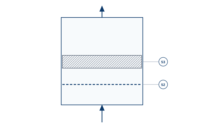
The gas leaves the secondary chamber upward and enters the adsorption chamber 5 directly, with no duct and no cooling between the two. Inside, a filter mesh 52 sits below an adsorption layer 53, which the embodiment specifies as activated carbon. Coarse dust is stopped by the mesh, and the gas then passes through the carbon.
Only after the adsorption chamber does the gas enter the flue-gas pipe 6, and only there is it cooled. The pipe carries a cooling layer 8 — a water jacket fed from tank 9 by pump 10 through inlet 81, returning through outlet 82. The description gives the jacket no other role.
The pipe then turns down into the filter tank 7, which holds limewater. The tank has a liquid inlet 71 at its upper middle, a liquid outlet 72 low on the side and a slag outlet 73 at the bottom, all with valves. Gas leaves at the side, enters the induced-draft fan 11, and is discharged to the stack 12.
End to end: primary chamber, secondary chamber, adsorption chamber, water-jacketed flue, limewater tank, induced-draft fan, stack. The fan is the last item before the stack, so the whole train upstream runs under negative pressure — a deliberate choice, and one of the better decisions in the design.
Reading the drawing
A small incinerator diagram of this kind is usually read for the shape of the equipment. This one is better read for the order of the stages, and the callout list makes that possible. The numbering is the patent numbering, so the redrawn figure can be checked against the original.
- 1 furnace body · 2 primary chamber · 3 secondary chamber · 4 blower · 5 adsorption chamber · 6 flue-gas pipe · 7 filter tank · 8 cooling jacket · 9 cooling-water tank · 10 cooling-water pump · 11 induced-draft fan · 12 stack.
- 21 waste inlet · 22 first air duct · 221 first air damper · 23 burner · 31 second air duct · 311 second air damper · 312 upper air branch · 313 lower air branch · 32 secondary-chamber door.
- 51 adsorption-chamber door · 52 filter mesh · 53 adsorption layer · 71 liquid inlet · 72 liquid outlet · 73 slag outlet · 81 cooling-water inlet · 82 cooling-water outlet.
Fig. 2 takes the adsorption chamber on its own, because that is where the order is decided. Gas arrives from below, meets the mesh first and the carbon second, and leaves at the top into the flue-gas pipe. There is no cooling before this vessel and no bypass around it.
Two details are easy to miss. The cooling jacket is drawn on the pipe, not on the furnace: the furnace body carries an insulation layer, the subject of claim 7. And the only doors are 32 on the secondary chamber and 51 on the adsorption chamber; the primary chamber has no clean-out opening. Ash removal from the primary chamber is not addressed anywhere.
What the 2017 design got right
Five decisions still look sound, and they are why the drawing repays study even though the order of the train has changed.
- The gas rises by itself. Primary below, secondary above, adsorption above that. The path follows buoyancy, so there is no duct fan between chambers and nothing to block with dust.
- The secondary air is split in two. Branches 312 and 313 admit air at the top and bottom of the secondary chamber instead of at one point. Two entry points distribute air across the section, reducing both an oxygen-starved pocket passing through unburnt and an oxygen-rich pocket overheating the refractory.
- The fan pulls rather than pushes. With the induced-draft fan at the end, every joint upstream is under negative pressure and leaks inward. The nine-step procedure uses that: the fan runs ten minutes before the burner, and the furnace is never pressurised.
- The maintenance points are actually drawn. Two inspection doors, three valved connections on the filter tank for liquid in, liquid out and sludge out, an insulated body. On a small incinerator these decide whether the unit survives its first year.
- Batch operation is honest about its limits. Nine steps, two hand valves, a burner, a pump and a person watching the stack. There is no control loop to fail.
None of that is clever engineering. It is the engineering of a small, cheap, manually operated furnace, and it is coherent on its own terms.
What has changed since 2017
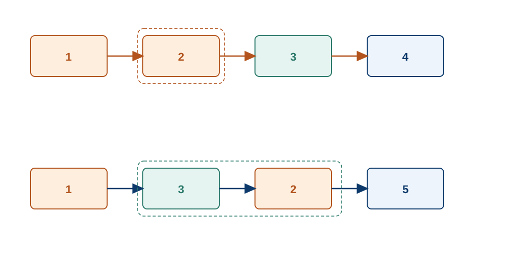
What has not aged is the furnace arrangement. What has aged is the order and the duties of the stages after it. Four differences are worth setting out, because each is a question a buyer should ask today.
Adsorption moved after cooling
In this document the carbon sits directly on top of the secondary chamber, so it sees gas at the temperature that chamber holds. Carbon is a fuel as well as an adsorbent, and in a hot oxygen-bearing gas it is consumed rather than merely loaded. Adsorption also weakens as temperature rises, so the hottest bed works furthest from what it is good at.
The order used now is the reverse: cool first, then inject powdered carbon into the duct or pass the gas through a fixed bed, then remove the dust in a bag filter, so carbon collected in the cake forms a contact bed. The patent merges two duties when it says the layer takes out dioxins, metal-oxide particles and remaining dust. Particles are a filtration duty; the mesh catches only the coarse fraction.
A water jacket is not a quench
The description states that the cooling layer prevents dioxins from re-forming at low temperature. The direction is right and the mechanism is not. Re-formation happens mainly between roughly 200 and 400 °C, and what governs it is the time the gas spends in that band, not the presence of a cold surface.
A jacket is an indirect surface exchanger. Its cooling rate is limited by surface area, gas velocity and the dust layer on the wall, and the document gives no inlet or outlet temperature and no transit time, so there is nothing to check it against. The drawing shows a tank and a pump on the water side and nothing else — no radiator, no cooling tower — so heat rejection during a long run is not addressed. Its real duty is more likely protecting the limewater tank and fan from hot gas.
Closing the window needs the gas through it quickly. An evaporative quench tower sprays water into the stream, and the latent heat of evaporation removes the heat without a surface for dust to foul — a different piece of equipment from a jacketed pipe.
Limewater is an acid scrubber
Limewater neutralises acid gases — sulphur dioxide, hydrogen chloride, hydrogen fluoride — well enough that wet scrubbing is still a standard answer for them. It does not do the rest of what the abstract lists.
- Nitrogen oxides: nitric oxide is only slightly soluble, so a wash removes very little. It is dealt with in the furnace, by staged air or reagent injection.
- Carbon monoxide: not a scrubbing target. It measures how completely the gas was burned.
- Dioxins and furans: poorly soluble, so a wash takes out a small fraction; the real removal is adsorption after cooling.
- Heavy metals: the dust-borne fraction leaves with the dust; mercury leaves as a vapour and needs an adsorbent.
- Volatile organic compounds: partly condensed or absorbed, not removed to the extent the abstract implies.
The tank in the drawing does not settle the question. It is a vessel with a conical bottom; no packing, spray header, gas distributor or demister is shown, so the contact arrangement is undefined and performance would depend on internals the document does not describe. The spent limewater and slag are a wastewater stream with no route here.
Filtration, burner and monitoring
Three absences are structural. There is no fabric filter, so fine particulate and the metals attached to it have only the mesh. There is no secondary-chamber burner. And there is no monitoring: no sampling port, no analyser, no temperature recorder, no control loop on either air duct — just two hand valves, manual ignition and a person watching the stack. There is also no ash handling for the primary chamber.
What a patent does not prove
An incinerator patent is not a performance certificate, and a Chinese utility model is a particularly thin kind of patent: it is not substantively examined. The grant certifies that the application met the formal requirements; it is not a finding that the design is novel over prior art, nor that it works better than an alternative. Reading a utility model as a quality mark over-reads what the office did.
A grant is also not a performance test. There is no measurement behind any statement: no stack test, no operating log, no capacity figure. When the description says the arrangement removes a list of pollutants, that is the applicant describing design intent, written to support the claims. It is not a result.
This document is expired, so it has no exclusionary effect: anyone may use the design. Three later patent documents cite it (CN109028081A, CN109173661A and CN113280355A), which shows later applicants read it, not that they endorsed it.
What the document is good for is what this article uses it for: a stage-by-stage disclosure of a small incinerator, drawn by the person who built it, that can be compared with current practice. Read as a datasheet it misleads. Read as a drawing it teaches.
What this means when you size a small incinerator
The walkthrough has one practical use: as a list of questions, none of which the patent answers. Four decide most of the specification.
- What is in the waste, and how much chlorine? PVC, clinical waste and some industrial streams raise the hydrogen chloride load, which sets the scrubbing duty and the material downstream.
- Which emission standard applies at the site? The limits and their averaging periods decide how many stages the train needs. Compare configurations A, B and C against those limits.
- Is there water, reagent and a route for wastewater? A wet train consumes lime or caustic, needs water, and produces a bleed that must be treated or taken away. Configuration A requires no process water; its suitability still depends on site limits and project verification.
- Who will operate it? A unit of this size is manual. Somebody must watch temperatures, charge at the right rate and notice the stack. A control panel instruments that duty; it does not remove it.
The configurations supplied now are set out on the incinerator pages, with configurations A, B and C as separate options. The order is explained in flue gas treatment in an incinerator; the cooling window in dioxin re-formation and the quench window; the combustion figures in why incinerators run at 850 °C for two seconds; the limits in the incinerator emissions chart. The 850 °C and 2.0 seconds figures are product data and standard figures, not the patent. Current configurations are specified separately, in the quotation and drawings.
Nothing here should be read as a statement that a current model is built to this 2017 design. The document is the starting point of the comparison, not the specification of what is sold.
Where to check the patent
The record is public: CN206600820U on Google Patents. The original is in Chinese, and the English text on that page is a translation, so the Chinese claims govern if the two diverge. The legal status shown there — expired, fee related — is the status quoted here.
The register entry reads: filed 2017-02-27, granted 2017-10-31, 7 claims, 2 figures, expired 2026-03-06. The filing was one of eight applications made that day. Everything after the expiry date is engineering history, a more useful thing to read it as than a product claim.