
On this page
Dioxin formation does not stop at the furnace
If your line is built around an 850 °C secondary chamber and a two-second residence time, you have bought the combustion half of the subject. What those figures destroy is set out in the article on why incinerators run at 850 °C for two seconds. This article covers the half that decides most stack results, from your chamber outlet to your stack.
Dioxin formation does not stop at the chamber outlet, because dioxins are not only destroyed and emitted — they are also made. Carbon, chlorine, oxygen and a metal-bearing surface are all there in your gas and its fly ash, and between roughly 200 °C and 400 °C those ingredients are assembled into dioxins and furans faster than the hot zone destroys them. That is why a line with a perfect chamber can still fail its stack test.
The two routes share a band and a surface, so one cooling duty and one adsorption duty answer both.
De novo synthesis of dioxins on fly ash
De novo means from new: the carbon skeleton is built from carbon already in your fly ash, not from a dioxin-like precursor. The reaction is heterogeneous — it happens on the particle surface, not in the gas — and it needs three things your gas supplies for free downstream of the chamber: unburned and soot carbon, chlorine, and a catalysing surface.
The catalyst makes this route sensitive to your waste. The ash surface carries metals, and the chlorides of copper and iron in particular are reported to promote the reaction strongly. Two wastes burned with identical temperature profiles and chlorine loads can give very different results. If your feed runs high in copper or iron, treat it as a higher-risk feed for re-formation.
The de novo synthesis of dioxins is an oxidative chlorination, so it also needs a little oxygen. A gas that has merely been cooled is still in the active band with every ingredient the reaction needs, so bringing a quench gauge reading down is not the same as closing the window.
The figures usually quoted put the fastest part of this reaction near 300 °C, with the band of concern extending over roughly 200 to 400 °C. Read them as a starting method, not a specification: they describe where the reaction is fastest on a typical fly ash, not a boundary where it switches on and off.
The precursor route: dioxins assembled from molecules already in the gas
The second route does not build the carbon skeleton from ash carbon. It starts from smaller chlorinated aromatic molecules — chlorobenzenes and chlorophenols — already in your gas, which condense onto the fly ash surface and couple there into dioxins and furans. The product is the same family; the raw material is different.
The two routes point at different problems, and different parts of what you buy. The precursor route needs a supply of chlorinated aromatics, a combustion problem: a chamber that destroys its organic compounds properly also stops supplying them. De novo synthesis needs the ash, the catalyst and the oxygen — a gas-train problem, answered in the cooling and filtration.
The 200 to 400 °C window and the rate of cooling
The reactions take time. Dioxins come from spending time in a temperature band, not from passing through it, so what you control is the time your gas spends inside the window, not the temperature at any single point. Gas crossing the band in a fraction of a second forms far less than gas drifting through it over minutes.
A single temperature reading is therefore a weak specification. A quench reporting a low outlet temperature says the gas is out of the window now; it says nothing about how long it took to get there, or whether part of the stream crept down a wall. Specify the temperature at each end and the residence time between them.
Load range matters as much as the design point. Gas velocity falls with the load, so a plant idling at a fraction of its rated throughput crosses the window more slowly, and a cooling section that looks adequate at the design point can be marginal at low load. Your plant will spend much of its life below that point, where the residence time in the window is longest.
Quench cooling in waste incinerators
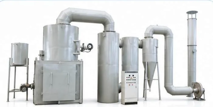
The commonest answer to the window is an evaporative quench. Water is sprayed into the gas stream, and the latent heat of evaporation takes the temperature down without a heat-exchange surface to foul; because the cooling happens in the gas itself, the drop is fast. The stages that follow it are in the article on flue gas treatment in an incinerator.
The alternative is heat recovery, and there the trade is real: a waste-heat boiler recovers sensible heat that a quench simply evaporates away, but it presents a large surface area and a long gas path, so your gas spends longer inside the window. If you want the boiler for the payback, ask how the design crosses the band.
Either choice fixes the inlet temperature of your filter. That figure is set by the bag material, and it has a useful side effect: a filter below the window leaves the collected ash outside the range that promotes further de novo synthesis.
After the quench: adsorption and the memory effect
Cooling reduces formation; it does not remove what has already formed. That duty falls to adsorption, and the usual arrangement is powdered activated carbon injected into the duct ahead of your bag filter, so the carbon builds into the filter cake and the gas passes through a bed of it rather than alongside it.
One behaviour is worth knowing before you specify the plant: dioxins adsorbed earlier can be released again when conditions change — a temperature swing, a load change, a stop and a restart — so a plant can emit more after an upset than its steady-state design predicts. Write continuous carbon injection, a cold ash hopper and the upset conditions into the specification and the acceptance test.
WHO-TEQ: where the stack figure and the limit come from
Dioxins are not one compound. The family runs to 210 congeners, of which the seventeen with chlorine in the 2,3,7,8 positions carry the toxicity. A stack result is a weighted sum: each congener is multiplied by a toxicity equivalence factor (TEF) and the products added, giving one figure in nanograms of toxic equivalent per cubic metre — ng TEQ/m³, written WHO-TEQ with the WHO factors. The factors are maintained by the WHO (1998, re-evaluated 2005, further consultation 2022).
Read the table as a conversion, not a ranking. In the congener names, CDD is a dibenzo-p-dioxin and CDF a dibenzofuran. Multiply each measured congener concentration by its factor and add: 100 ng/m³ of a congener with a factor of 0.01 counts as 1 ng TEQ/m³, the same as 1 ng/m³ of 2,3,7,8-TCDD.
Wide table: scroll sideways to see every column.
| Congener | WHO 2005 TEF |
|---|---|
| 2,3,7,8-TCDD | 1 |
| 1,2,3,7,8-PeCDD | 1 |
| 1,2,3,4,7,8-HxCDD | 0.1 |
| 1,2,3,6,7,8-HxCDD | 0.1 |
| 1,2,3,7,8,9-HxCDD | 0.1 |
| 1,2,3,4,6,7,8-HpCDD | 0.01 |
| OCDD | 0.0003 |
| 2,3,7,8-TCDF | 0.1 |
| 1,2,3,7,8-PeCDF | 0.03 |
| 2,3,4,7,8-PeCDF | 0.3 |
| 1,2,3,4,7,8-HxCDF | 0.1 |
| 1,2,3,6,7,8-HxCDF | 0.1 |
| 1,2,3,7,8,9-HxCDF | 0.1 |
| 2,3,4,6,7,8-HxCDF | 0.1 |
| 1,2,3,4,6,7,8-HpCDF | 0.01 |
| 1,2,3,4,7,8,9-HpCDF | 0.01 |
| OCDF | 0.0003 |
That is the unit your limit is written in, and it is worth being precise about where it comes from. The WHO sets the health basis, not the stack figure: the 1998 expert consultation established a tolerable intake of 1–4 pg TEQ per kilogram of body weight per day. Regulators translate that basis into an emission limit — the EU Industrial Emissions Directive (2010/75/EU) puts 0.1 ng TEQ/m³ on waste incineration as a mean over a 6–8 hour sampling period. The same unit appears in the chart of incinerator emissions, where medical and hazardous waste incineration carries 0.5 ng TEQ/m³ and municipal solid waste incineration 0.1 ng TEQ/m³. Dioxin control in medical waste incinerators is therefore a question about the whole chain: cooling that leaves the window quickly, then adsorption that catches what formed anyway.
One property shapes how you use it: the figure is a mean over a defined sampling period, not a spot reading, so it describes your plant under normal operation rather than its worst minute. A compliant figure does not prove the cooling design is generous — which is why the cooling section is designed from the temperature profile and the residence time, and the stack figure only confirms it.
Common mistakes
- Specifying a quench outlet temperature and nothing about the time the gas spends in the window. Temperature says where your gas is, not how long it took to get there.
- Slowing the quench cooling in waste incinerators for more heat recovery without asking what the gas passes through on the way down; heat recovery and dioxin control pull against each other in the same band.
- Treating 850 °C and two seconds as the whole dioxin answer. They govern destruction in the chamber, not what is made afterwards.
- Letting the filter inlet temperature drift up, so the collected ash moves back towards the window it was removed from.
- Ignoring the ash chemistry. A feed high in copper or iron gives the fly ash a more active surface, and the same profile then produces more.
- Sampling once and treating the result as a plant property. The figure is a mean over a period, and only meaningful with the period, load and conditions attached.
Self-check before the cooling section is specified
- Is your gas temperature known at every point from the chamber outlet to the filter inlet, not at the two ends only?
- Is the residence time between the top and the bottom of the window stated as a design figure?
- Has the cooling been checked at the lowest load the plant will run, where the gas is slowest?
- Is the filter inlet temperature matched to the bag material and held below the window?
- Is the adsorbent injection rate sized for the re-formation load, and is it a continuous duty?
- Are start-up, shutdown and load-change conditions covered, given that adsorbed material can be released again?
- Is the target stack figure expressed in ng TEQ/m³ over a stated sampling period, and is it a WHO-TEQ figure?
From a temperature profile to a stack figure
Dioxin re-formation in flue gas is controlled by a chain rather than by a device: destruction in your chamber, a cooling section that takes the gas out of the active window quickly, and an adsorption stage that catches what formed anyway. The chart of incinerator emissions sets the limit the chain has to meet, and the article on flue gas treatment covers the stages after it. The cooling arrangement, the adsorbent rate and the filter duty follow from the waste composition and the standard in force — confirmed with us for your waste and your limit.